Knocking / rattling inside primary drive case + backfire

I would say the spacers are to position the rotor centrally within the stator for maximum alternator power. As long as you keep parallax in mind, the distance from the rotor doesn't matter. It's probably not accurate anyway unless you've checked it with a dial gauge and degree wheel.

Yes, to position the rotor close to the timing scale in order to get the maximum available alternator output that marshg246 mentioned in post #124.
 
Thanks Tornado, that’s really useful. I think I’ll loosen it a bit in that case. I used some finger force to test the deviation.
That was my impression from one of your earlier images...just looked like there was some fair amount of force being applied to chain. I recall expecting it to have hard stop as force is applied, but instead it kind of loads up and keeps deflecting a certain amount. Assume its some slack in the chain links and even some amount of clutch basket "wobble" on the bearing etc.

EDIT: Just re-watched the second video you posted, the one with the primary opened...and when you deflect the chain, it certainly looks too tight to where I set mine. Again, a light up/down finger motion to see how far up & down it deflects seems to be the the right method. When I had it too tight, like what I see in your video, the clutch engagement to neutral with bike not moving was difficult and others told me to slacken to protect the clutch bearing and GB bearing.
 
Last edited:
Fair enough but it was a reply to M-Hawk's comment about the correct placement of shims.
Understood and good reply it was, but I was about to tell him my opinion to ignore them so I didn't want to dispute you, but I did want to provide my opinion without anything negative about your reply.
 
You probably have this figured out, but here's what I would do.

With the primary chain off and no key, see if the front sprocket pushed hard on by hand will turn. If so, the crank or sprocket taper needs attention. Maybe a burr, maybe worn - hard to say without seeing it. If it is OK, check that the key is a tight fit in the crank and in the sprocket. If so, you can put the chain and sprocket back on being sure that the key stays in place (they often slip backwards)

Put this part on with the flat side towards the sprocket.

Knocking / rattling inside primary drive case + backfire


Check that the rotor key is sung in the crank and rotor. If so, put the rotor on and tighten - real tight. Ignore any other parts that were on the crank when you started.

When this is all done, you can measure the distance between the rotor timing marks and the back of timing indicator. With that measure measurement in hand, yuo can determine what shims you want to bring the rotor further out - personally, I don't bother.
 
When this is all done, you can measure the distance between the rotor timing marks and the back of timing indicator.

Apparently, there is no timing scale (Post #135) but don't as yet know if that's because it was wiped off due to the 6mm rotor spacer (but no damage to that particular rotor) or removed because of it.
 
As already mentioned, the crank pulley should NOT be loose.
Looking at that bodged rotor key, i would suspect the same on the pulley.
Complete disasembly required. Good time to clean up clutch plates while you're there.
Careful reasembly with factory bits, you should be good to go.
The plus side is you'll have a full understand of the primary. Win Win...
 
Apparently, there is no timing scale (Post #135) but don't as yet know if that's because it was wiped off due to the 6mm rotor spacer (but no damage to that particular rotor) or removed because of it.
I saw that and was not sure he knew where to look. In #136 you told him where to look but I'm still not sure if he understood. There's a lot going on for someone new to all this and with trying to solve a problem at the same time. He didn't mention seeing where it would go if missing - could be completely worn away, simply removed by a previous owner, there and he didn't notice (unlikely given the spacer), or it could have the flat kind that cNw supplies with their e-start kit.
 
You probably have this figured out, but here's what I would do.

With the primary chain off and no key, see if the front sprocket pushed hard on by hand will turn. If so, the crank or sprocket taper needs attention. Maybe a burr, maybe worn - hard to say without seeing it. If it is OK, check that the key is a tight fit in the crank and in the sprocket. If so, you can put the chain and sprocket back on being sure that the key stays in place (they often slip backwards)

Put this part on with the flat side towards the sprocket.

View attachment 103518

Check that the rotor key is sung in the crank and rotor. If so, put the rotor on and tighten - real tight. Ignore any other parts that were on the crank when you started.

When this is all done, you can measure the distance between the rotor timing marks and the back of timing indicator. With that measure measurement in hand, yuo can determine what shims you want to bring the rotor further out - personally, I don't bother.
I was thinking about this spacer too.

In one of the pics and vids posted, the shoulder on the crank looks almost flush with the face of the sprocket.

So it might be that if this spacer was wrong / missing / fitted backwards then the torque on the rotor nut may have been clamping the rotor to the crank shoulder?

The purpose of the machined spacer is to ensure that the large ID faces the sprocket in order to ensure that the torque applied to the rotor nut is actually clamping the sprocket onto the taper.

@ the OP, please look at the sprocket face / crank shoulder area ref the above point. Also, please tell us how tight that rotor nut was when you removed it, it should be VERY tight. As already mentioned, unlike Triumphs that have a splined crank for the sprocket location, the Norton relies totally on that taper, and it’s the rotor nut that keeps that taper tight.

Having come this far, I strongly suggest you remove the sprocket to check the condition of that taper.
 
The purpose of the machined spacer is to ensure that the large ID faces the sprocket in order to ensure that the torque applied to the rotor nut is actually clamping the sprocket onto the taper.
Spacer '31' should be fitted "with the recess outwards..." as it says in the factory manual section C34, 21 (to accommodate the rotor Woodruff key). Also, see post #144.

Edit: Also, I believe the rotor shims are 3/4" I/D and they go between the sprocket and the spacer that the crank taper would not fit through.
 
Last edited:
Spacer '31' should be fitted "with the recess outwards..." as it says in the factory manual section C34, 21 (to accommodate the rotor Woodruff key). Also, see post #144.

Edit: Also, I believe the rotor shims are 3/4" I/D and they go between the sprocket and the spacer that the crank taper would not fit through.
Good correction LAB !

But I‘d still want to check that the rotor isn’t being clamped to the crank shoulder instead of the sprocket and taper, ie if the taper has been re cut or lapped in the past and is allowing the sprocket to sit further inboard than it should.
 
Last edited:
Thanks for the input everyone. You're really helping to get me through this. I'm mechanically minded, and happy to tackle new things but it's tough going when someone has done work prior that is out of spec or abnormal.

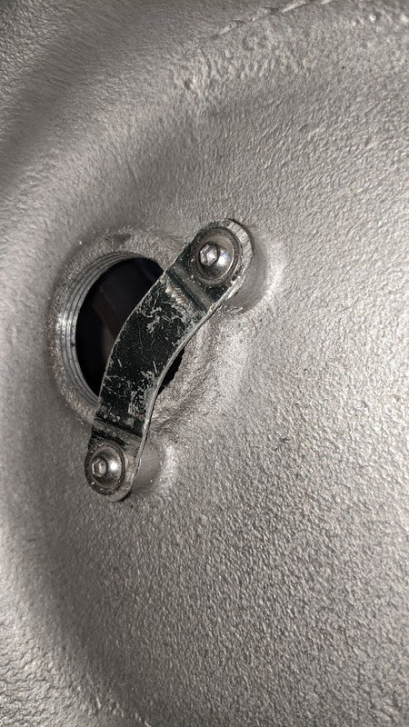
Case in point (pun intended) - I'm guessing that these two spots near the inspection hole are where the timing scale screws would normally go? So, to answer an earlier question - I don't have a timing scale and it looks like mounting one is going to be a little tricky.

Knocking / rattling inside primary drive case + backfire
 
I agree with posts #144, #146 and #148 as a plan of action. It's got to be stripped down for peace of mind as much as anything.

I'll get a sprocket puller ordered. I already have the clutch tool.

Having come this far, I may as well get the correct locking plates (tab washers) and change the inside case mountings as well.
 
You can buy the timing scale for MK3 , which have elongated holes (thus enabling you to move it till it is exxactly at the right point !) then drill and fit with self tapping screws , may be some little spacers will be usefull between the scale and your case !
 
Case in point (pun intended) - I'm guessing that these two spots near the inspection hole are where the timing scale screws would normally go?

Yes, the plate would have been attached with hammer drive screws...


I'll get a sprocket puller ordered.

Is the woodruff key in your picture the one from the rotor slot? I thought it would be from the crank taper.

If the engine sprocket is as loose as you demonstrated in your video then it will probably come off without needing the puller.
 
Yes, the plate would have been attached with hammer drive screws...


Is the woodruff key in your picture the one from the rotor slot? I thought it would be from the crank taper.

If the engine sprocket is as loose as you demonstrated in your video then it will probably come off without needing the puller.
Yes L.A.B. - the key in the picture is the rotor key.

Good point on the sprocket. I'll see if I can yank it off by hand this afternoon.
 
There may be not enough thickness left on the outer cover for the hammer self drives to hold the timing scale on.

When faced with the same issue I drilled and tapped for short M4 allen flanged head screws. I flattened the old timing scale but a MK3 would do the job and be adjustable.

Knocking / rattling inside primary drive case + backfire
Thanks for the photo kommando - that's exactly what I envisaged doing.
 
Purely a guess. A British motorcycle owner other than Norton might have been annoyed at the rotor sitting so far in and made a shim to fix that and got rid of the timing scale which would then interfere. Using a degree wheel, you could set the engine at 28 (or whatever you want) degrees before TDC, and mark the stator to match. Then you would have a timing mark to use in the future.
 
Back
Top