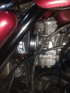
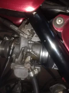
Based on what I am reading here a single 32mm carb is flowing roughly 145 CFM and with the commonly available 2 into 1 manifolds each cylinder depending on the engine size needs 80 to 90 CFM of flow at 6000 RPM or peak power (the manifolds don't make power over 6000 rpm). A 34mm carb is 165CFM which is 2x flow needed for a 750 at 6000 RPM with 100% VE, which is why it is a common set up. An 850 would benefit from an 36mm carb with this logic. If the 6000 rpm limit could be pushed to 7500 an 850 at 100% would benefit from a single 40mm carb.
Dual carbs are a bit more efficient and the manifold design for them is significantly efficient. The same 850 with individual carbs can gain an extra 1000 to 1500 RPM+ (horsepower needs RPM) which takes the CFM needs of the engine from 90 to 115 CFM at 100% efficiency.
Please someone correct my math or my information if I get something wrong, I am very eager to learn more about this.
To make any headway here we have to start by making everything as simple as possible, but no simpler, and the 1st item might be, that if we state an airflow we have to know if it is theoretical, was taken on a flow bench, or whatever. If taken on a flowbench we have to state either the test depression it was measured at, or the test depression it was corrected to. Commonly used flow bench test pressures are 10” and 28” water column, but can be literally any pressure you want so long as you say what the test pressure was. We can’t say something like the following - an X size Mikuni carb flows Y cfm. We don’t know anything about the testing/configuration/pressure it was flowed at, and lacking these particulars the information is totally meaningless, since we don’t know what to compare it to.
As I mentioned earlier in this thread, the airflow of heads commonly run across here include a continuum ranging from stock heads that flow ~ 75 cfm @ 10” WC to the fully developed big-valve heads on factory castings that flow up to 90 cfm at 10” WC. Another absolutely critical consideration when giving an airflow value is to state the items attached to the head when it was tested, e.g., a velocity stack attached directly to the port, a manifold with a velocity stack on it, or a combination of parts such as a manifold, 32 mm carb and ham-can air cleaner. If these parameters are unknown then we’re mixing apples and oranges and nobody will ever be able to decipher the code. In the 1st sentence of this paragraph, I gave airflow values but didn’t say what the test set-up was, and it happens to be a velocity stack attached directly to the port (a radiused entry assures incoming air is active on full duct circumference).
Let’s say we’ve now defined a flow regime of 75-90 cfm @ 10” WC for heads having a velocity stack attached directly to their port and with the valve lifted 30% of its diameter. Maybe we want to next estimate, not measure, how much air a series of different size carbs might pass. We know that a perfectly stream lined orifice passes ~ 87 cfm/sq in at 10” WC, and that a carb isn’t a perfectly streamlined orifice, so will pass less air. But, let’s see what they’d pass if they could reach entitlement, i.e., the most air a carb of these dimensions could possibly pass at a 10” WC depression.
Orifice Size (mm) | Airflow Entitlement at 10” WC (cfm) |
32 | 109 |
33 | 115 |
34 | 123 |
35 | 130 |
36 | 137 |
The above discussion provides a rudimentary approach to thinking about cylinder head airflow and carbs that might support it. Experience tells us (our friends here on the forum that use 35 mm FCRs on 90 cfm heads) that whatever the flow of a 35 mm carb is (less than 130 cfm at 10" WC), it is well suited to feeding the 90 cfm head.
If the goal of measuring/quantifying airflow is to estimate power output (efficiency) of a specific combination of induction system parts, then we need every single component present when performing flow tests. For the remainder of this document any airflow value recited is assumed to be taken at 10” WC with the IN valve lifted 30% of its diameter.
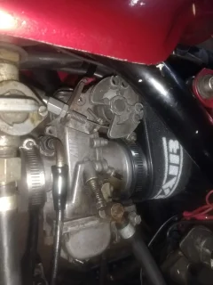
Let’s now consider a fictitious example of a head that flows 75 cfm with a radius entry on the port. Let’s now add the intake manifold with a radius entry on it and retest. Oh my, now it only flows 72 cfm so the intake manifold cost us 3 cfm. Next, we add the carburetor with throttle positioned wide open and no radius entry (carbs are generally configured with some semblance of a radius entry on the horn end). The retest shows that the carb cost us an additional 4 cfm, so our 75 cfm test head is now flowing 68 cfm with a manifold and carb present, so we’ve already lost ~ 10% of the starting airflow. But we still don’t have an air cleaner on the system, so let’s add our favorite old ham-can AC to the system and retest with the full induction system present. Well, turns out the ham-can isn’t our friend either because now we are flowing 60 cfm (ham-can cost an additional 8 cfm), so the full induction system has cost us 20% of the airflow we started with. And it is this final airflow that relates to the potential power the engine can make. If we're just doing quick and dirty airflow tests, a radius entry on a port will suffice, but if we are attempting to relate airflow to HP, we need the full induction system in place when we test.
The point of the foregoing is to illustrate that if we intend to use the relationship between airflow and HP, we need all the intended induction system components present to test. Introducing any “reasonable size” carb to an induction system will cause an airflow loss, as will the addition of an air cleaner. The loses may be significant or incremental but they will nevertheless always be there and be measurable. The exception to the previous statement would be a fuel injected system where the throttle body can be very large and no significant sized venturi/throttle shaft/restriction is present to impede airflow.
I hope the foregoing might clarify a few items relating to discussing and measuring airflow.

