Thanks for visiting Access Norton
- Guest view limit reached
- Create a free account (more details)
- Already a member? Click here to login
You are using an out of date browser. It may not display this or other websites correctly.
You should upgrade or use an alternative browser.
You should upgrade or use an alternative browser.
TW wrecks a perfectly good Commando etc.
- Thread starter Time Warp
- Start date
Well I'll be damned! A telehydraulic alternator rotor alignment tool.
Time Warp
.......back to the 70's.
- Joined
- Dec 3, 2012
- Messages
- 3,727
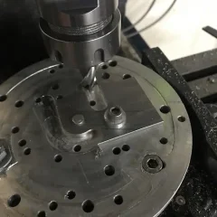
I got to setting up for welding.
What drongo gets (remembers) the small electronic angle /bevel box to check things after making the parts by what looked spring vertical by eye.
I had to laugh, the top plate no matter how I wanted it to be right (or would take close) is miles out and the spring to rearward so would clash with the frame cross tube.
 Doh.
Doh.
Take two.... It keeps you honest.
What drongo gets (remembers) the small electronic angle /bevel box to check things after making the parts by what looked spring vertical by eye.
I had to laugh, the top plate no matter how I wanted it to be right (or would take close) is miles out and the spring to rearward so would clash with the frame cross tube.
Take two.... It keeps you honest.
cliffa
VIP MEMBER
- Joined
- May 26, 2013
- Messages
- 4,422
Intriguing. I've been wracking my little brain working out how this will function. Looking forward to the next instalment
Time Warp
.......back to the 70's.
- Joined
- Dec 3, 2012
- Messages
- 3,727
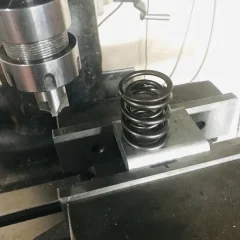
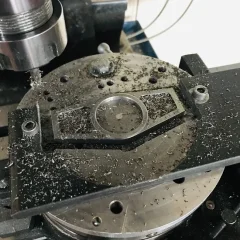
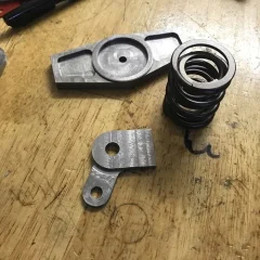
The recessed odd shape plate will weld between two of the new brackets (on the right)
The smaller hole will end up 1/4" so a UNF bolt and nut can be used to avoid any chance of that spring holder rotating.
The lower cup to be welded to the frame cross tube has a machined recess for the spring also and that (recess) can also be used for locating a spacer/pre loader as necessary.
Its rubbish day so lawns and garden come first.
Time Warp
.......back to the 70's.
- Joined
- Dec 3, 2012
- Messages
- 3,727
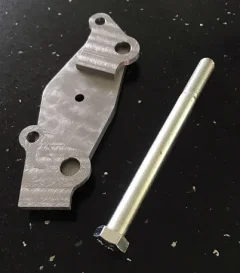
I needed a longer zinc 3/8 UNF bolt so that put another 241 kms on the ATDCT's odometer finding one but it was a sunny day with a breeze.
We can only guess how the top bracket is attached on the JC Commando but will assume it attaches at the lower Isolastic bracket bolt location.
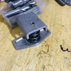
Something like this, with a check at vertical to the lower frame rail the spring will now have around a 4mm + clearance to the frame cross tube which will get the lower cup.
The wings are 4mm (machined from 6mm bar) thick, the spring holder is hopefully not going to bend and contact the engine cases.
I read in another thread the engine is somewhere around 90 lbs but that might not be the weight the spring has to contend with, less perhaps.
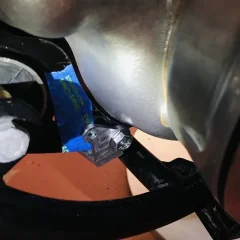
Because this is eventually a stock Commando these sort of hidden modifications are about it.
We can only guess how the top bracket is attached on the JC Commando but will assume it attaches at the lower Isolastic bracket bolt location.
Something like this, with a check at vertical to the lower frame rail the spring will now have around a 4mm + clearance to the frame cross tube which will get the lower cup.
The wings are 4mm (machined from 6mm bar) thick, the spring holder is hopefully not going to bend and contact the engine cases.
I read in another thread the engine is somewhere around 90 lbs but that might not be the weight the spring has to contend with, less perhaps.


Because this is eventually a stock Commando these sort of hidden modifications are about it.
cliffa
VIP MEMBER
- Joined
- May 26, 2013
- Messages
- 4,422
Aha, everything becomes clear !!
Looking at the pictures 74ok enhanced it's easier to see Jim's handywork. I hadn't realized before that it's using the lower ISO mounting bolt for the upper support.

 www.accessnorton.com
Looking at the pictures 74ok enhanced it's easier to see Jim's handywork. I hadn't realized before that it's using the lower ISO mounting bolt for the upper support.

New use for a Kibblewhite Performance valve spring (2013)
Getting ready for my upcoming 4-5000 mile road trip and thought I would play with reducing vibration on the road. The iso rubbers were replace a couple years ago but with heavy 880 pistons and steel rods the bike has never been as smooth as it was originally. Now after a couple years the...
Time Warp
.......back to the 70's.
- Joined
- Dec 3, 2012
- Messages
- 3,727
I think it said in that original thread JC had no Isolastics in the housing just a spacer tube (iirc) and that panhard bar.
It occurred to me (The bracket is done and will do some final work on it tomorrow) having the Isolastics in place will reduce the needed spring pressure.
Maybe in my case all it will do is maintain things centrally which I need for the head steady but not do anything for vibration.
I think I allowed around 6mm of movement to contact (3mm any direction) spindle to bore in the frame hanger bracket , it might be like a jack hammer if not enough, hopefully the spring will stop that.

cliffa
VIP MEMBER
- Joined
- May 26, 2013
- Messages
- 4,422
It would be really interesting to compare with and without ISO's.I think it said in that original thread JC had no Isolastics in the housing just a spacer tube (iirc) and that panhard bar.
It occurred to me (The bracket is done and will do some final work on it tomorrow) having the Isolastics in place will reduce the needed spring pressure.
Maybe in my case all it will do is maintain things centrally which I need for the head steady but not do anything for vibration.
I think I allowed around 6mm of movement to contact (3mm any direction) spindle to bore in the frame hanger bracket , it might be like a jack hammer if not enough, hopefully the spring will stop that.
View attachment 84040
Time Warp
.......back to the 70's.
- Joined
- Dec 3, 2012
- Messages
- 3,727
Maybe the front Isolastic tube could be mounted in the rotary table chuck and a unknown size and number of holes could be drilled through the outer rubbers.
A bit like sitting on the fence, less rubber more spring.
JC did say it was very smooth.
Maybe there could be another one of these spring units above the cradles Isolastic tube.
My biased belief is the Sunbeam S7 / S7 Deluxe / S8 over the period 1946 to 1956 was the inspiration for the rubber mounted Commando engine but have wondered for the future if some of the Commando's Isolastic parts could be adapted to it.
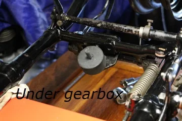
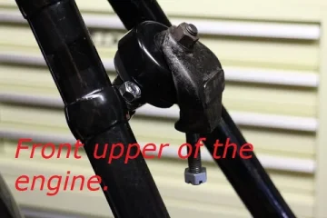
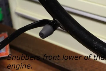
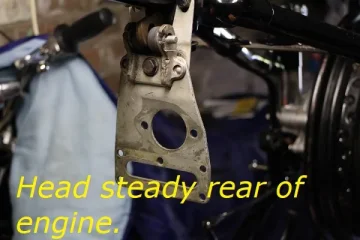


cliffa
VIP MEMBER
- Joined
- May 26, 2013
- Messages
- 4,422
I love those Sunbeam S7's, they were so advanced for the time. What a shame they weren't a bigger hit. I believe the early examples engines weren't rubber mounted and shook like billy-o. Are they 360 cranks?
Before Meriden closed they developed sort of Isolastic system for the Bonneville using (I think) Mini Metro engine mounts with the engine just sat on top of them like a car engine would be. It was reputed to be very good but I think they only sold a few before it folded.
Before Meriden closed they developed sort of Isolastic system for the Bonneville using (I think) Mini Metro engine mounts with the engine just sat on top of them like a car engine would be. It was reputed to be very good but I think they only sold a few before it folded.
Time Warp
.......back to the 70's.
- Joined
- Dec 3, 2012
- Messages
- 3,727
Yes a one piece 360 crankshaft with external car like flywheel.
The story I read online was the first model (S7 1946 to 1948) went to the South Africa Police (iirc) and vibrated so badly they were sent back where the rubber mounting was added.
There is a long spring in the top frame tube for the cantilever linked seat which adds some comfort and a little more anti vibration.
Perhaps one problem was they detuned the original versions (cross flow head perhaps) instead of uprating the final drive (and many of the wear failures were oil related) that or the 100 mph of that original version could extinguish your smoking pipe at speed and it was toted as a 'gentleman's tourer.
The 1970's Suzuki 750 two strokes had steel sleeve rubber bushings in the engine case mounting lugs (which can be fit to the 1974 and 1975 Kawasaki 750 two strokes having enough material to do so (unlike the 1972 and 1973 cases) so vibration was not just Brit bikes.
Last edited:
Time Warp
.......back to the 70's.
- Joined
- Dec 3, 2012
- Messages
- 3,727
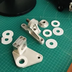
The bracket is done besides some filing on the sides, the fillets on the side welded up (ER70 wire) nicely but I hit the corners with a 5mm radius cutter anyway (set up took longer than the cuts which is often the case)
It could have been more basic (less time) but since I am copying a JC idea I thought it better (an excuse to) flash it up a bit.
It is reasonably light weight.


It could have been more basic (less time) but since I am copying a JC idea I thought it better (an excuse to) flash it up a bit.
It is reasonably light weight.
Last edited:
Fast Eddie
VIP MEMBER
- Joined
- Oct 4, 2013
- Messages
- 22,698
The swinging arm area is not simple on the Triumph AV frames though as Triumph wanted to allow the swinging arm to move but not mount it to the moving engine like Norton did.Looks like you have a nice collection !! Are those extended studs?
I've just found a picture of the lower rubber mounts on the T140AV. Apparently Bernard Hooper was also involved. It's pretty simple if you compare it to a Commando.
View attachment 84051
I think the biggest potential problem with such AV frames, and I think the same happened back in the day with Commandos, is that the smoothness makes the rider think that 8,000rpm is ok !
Similar threads
- Replies
- 13
- Views
- 2,424
- Replies
- 34
- Views
- 3,916

