1975 Commando 850 restoration

Yes. If you have a 12V battery you can check the solenoid operation by connecting the battery to the WR ('S') terminal and ground or the metal plate of the solenoid when you should then hear it click.
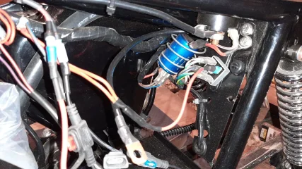
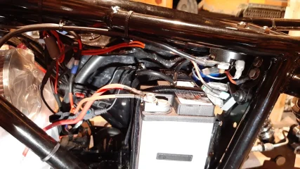
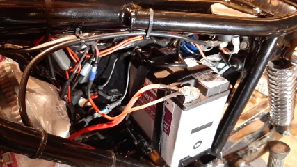
Thank you very much for sorting this out for me. I will insulate the double red ring connector also, thanks.
 
L.A.B. I've insulated WP as suggested. I didn't fit the double red harness positive ring terminal but I did connect it to the rectifier. Is this acceptable?
 

Attachments

  • 1975 Commando 850 restoration
    20210621_193352.jpg
    374.3 KB · Views: 241
Cleaned up my seat. I think it came out pretty good. Before and after. The gunk that was on the seat was the remains of the back of my owners manual. It all came off by tedious scraping with my fingernail. PITA!
 

Attachments

  • 1975 Commando 850 restoration
    20210615_122418.jpg
    599.3 KB · Views: 214
  • 1975 Commando 850 restoration
    20210616_195755.jpg
    491.5 KB · Views: 201
  • 1975 Commando 850 restoration
    20210616_195821.jpg
    585.2 KB · Views: 196
  • 1975 Commando 850 restoration
    20200315_145858.jpg
    301.6 KB · Views: 187
Major progress! All the wiring is complete, pending a question to L.A.B. The hardest part was stuffing all that mess of wiring into the headlamp shell.
 

Attachments

  • 1975 Commando 850 restoration
    20210616_195659.jpg
    551.6 KB · Views: 205
As it sits now.
 

Attachments

  • 1975 Commando 850 restoration
    20210621_193215.jpg
    367.1 KB · Views: 211
  • 1975 Commando 850 restoration
    20210621_181441.jpg
    493 KB · Views: 220
  • 1975 Commando 850 restoration
    20210621_181528.jpg
    464.9 KB · Views: 235
I know everyone gets their brake rotors Blanchard ground but I chose to have my nephew Ben turn them on his lathe. Just enough to take the rust off. Anyone else done this? Concerns?
 
I didn't fit the double red harness positive ring terminal but I did connect it to the rectifier. Is this acceptable?

The standard Mk3 rectifier is the 2-diode 2DV 406 which doesn't have (or require) a ground (so there's no red wire in the harness section to the rectifier), therefore, a ground connection to the (+) terminal of the encapsulated 4-diode rectifier in your picture isn't necessary but I believe it does no harm.
1975 Commando 850 restoration
 
Last edited:
I know everyone gets their brake rotors Blanchard ground but I chose to have my nephew Ben turn them on his lathe. Just enough to take the rust off. Anyone else done this? Concerns?
The concern I would have ( for the front rotor at least) is trueing the rotor faces to the mounting face ( where the rotor meets the wheel hub) as these rotors are non floating and you will want to eliminate any swashplating.
 
I brought a Mk 3 home on Sunday and it had that same sissy bar on it along with a king/queen seat! Sat in a shed for 11 years .
I’m going to start a thread of my own. I already have a 73 850 that I’ve owned since 1978.
Good luck with your build. Be prepared to SPEND some money! All worth it though.
 
Got some pieces back from my powdercoater dude. Nice!
 

Attachments

  • 1975 Commando 850 restoration
    20210624_202907.jpg
    384.7 KB · Views: 176
  • 1975 Commando 850 restoration
    20210624_202937.jpg
    421.2 KB · Views: 182
Front end all complete except for fluids.
 

Attachments

  • 1975 Commando 850 restoration
    20210625_200621.jpg
    386.2 KB · Views: 200
  • 1975 Commando 850 restoration
    20210625_200528.jpg
    410.4 KB · Views: 200
  • 1975 Commando 850 restoration
    20210625_200700.jpg
    387.6 KB · Views: 211
  • 1975 Commando 850 restoration
    20210625_200710.jpg
    395.9 KB · Views: 200
Installed a new battery and tested my electrical system with mixed results. Turning the ignition switch two clicks to the right, this is what I have. I have hi and lo beam headlight, taillight, and all my console lights. My horn and neutral switch are both working also. Turn signals are installed on the front but do not work properly. I have read that problems with your turn signals are often resolved with a proper ground. I'm going to order new turn signals for front and rear and install a proper ground to see if that cures the problem. I haven't tested brake lights because the system isn't filled with fluid yet. All and all, not bad so far.
 

Attachments

  • 1975 Commando 850 restoration
    20210626_175604.jpg
    300 KB · Views: 171
  • 1975 Commando 850 restoration
    20210626_175625.jpg
    304.6 KB · Views: 175
  • 1975 Commando 850 restoration
    20210626_175329.jpg
    343.1 KB · Views: 166
  • 1975 Commando 850 restoration
    20210626_175342.jpg
    366.4 KB · Views: 154
  • 1975 Commando 850 restoration
    20210626_175335.jpg
    332.3 KB · Views: 166
Installed my VIN plate today. Used the top frame tube to form the bend in the plate prior to install. Looks good.
 

Attachments

  • 1975 Commando 850 restoration
    20210627_162139.jpg
    275.5 KB · Views: 163
  • 1975 Commando 850 restoration
    20210627_162211.jpg
    228.7 KB · Views: 167
More progress. Installed my rear fender and taillight assembly. This bike is looking great so far!
 

Attachments

  • 1975 Commando 850 restoration
    20210627_161651.jpg
    316.3 KB · Views: 162
  • 1975 Commando 850 restoration
    20210627_161640.jpg
    253.3 KB · Views: 153
  • 1975 Commando 850 restoration
    20210627_161601.jpg
    406 KB · Views: 153
  • 1975 Commando 850 restoration
    20210627_161524.jpg
    422.5 KB · Views: 170
Turn signals are installed on the front but do not work properly. I have read that problems with your turn signals are often resolved with a proper ground. I'm going to order new turn signals for front and rear and install a proper ground to see if that cures the problem.

Your picture seems to show the front signals wired as running lights as both are on together or something isn't connected correctly (or are they LED bulbs as that can result in both sides working simultaneously unless the warning light bulb wiring is modified?) which isn't standard so are unlikely to work properly in that configuration, also unlikely to flash unless the rear signals are connected and LED bulbs would need an LED flasher relay or additional resistors.

The sleeve connection at the bottom of the headlamp shell is there to provide a ground to harness red for the front direction indicators and is not a 'headlamp ground' as often thought so ensure that the connection between the shell and harness red is secure.

Also, what is the additional thinner (but heavier than standard?) gauge red wire connected to battery positive (for electronic ignition perhaps?)?
Connecting a thinner gauge (than the starter positive cable) wire would defeat the object of not connecting the harness positive ring terminal if the electrical system can use it as a ground/return to battery positive (unless it has a fuse to prevent the starter motor current burning the wire out?) unless, for instance, it is only a ground for electronic ignition where it has no connection to the harness or 'frame'.
 
Last edited:
Back
Top