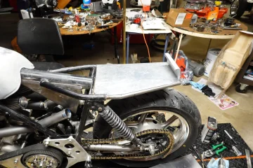
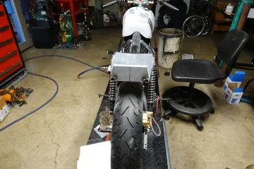
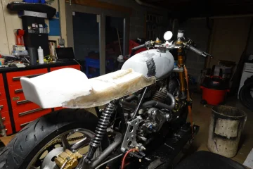
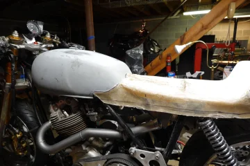
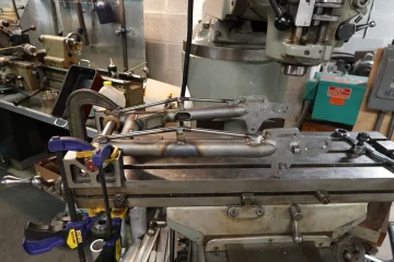
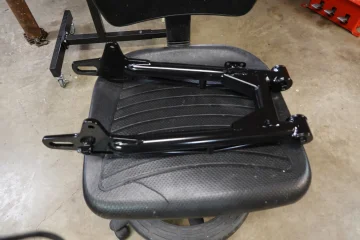
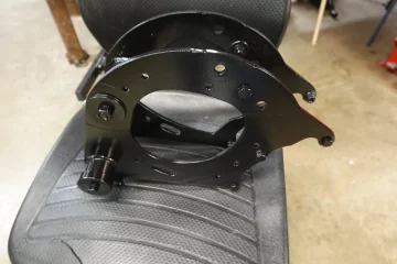
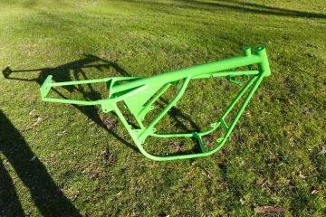
Quick ck on the swing arm before filling cut out for tire and then off to the powder coater!
View attachment 104358
Hi Gene, I noticed the final swinging arm has a rectangular transverse member (as per 850 Commando), while the one pictured above has a circular one. Did you work on two different swinging arms?
Also, could you please explain the advantage of the tie rod which acts like a rope or wire? Provided the tie rod is well anchored and the pillar mount doesn't collapse, it will provide a nonlinear stiffening effect for the tubes in the vertical plane, thus limiting bending in that plane.
However, given the location of schock absorbers close to the wheel spindle, bending of the (stock) swinging arm in the vertical plane is rather marginal.
In my opinion, stiffening the swinging arm against torsion and horizontal bending would be far more desirable.
Did you reinforce the swinging arm internally at the tie rod pillar? Thin tubes will benefit from a stiffening plate crossing the tube or encirceling it in the style of a collar.
Another issue is the detrimental affect of welding a heat treated swinging arm. You will have to monitor the S/A for development of cracks.
- Knut
Edit: Conservatively, a swinging arm can be considered a simple supported beam of length L and flexural rigidity E*I subjected to an end moment (M). The latter is the result of the vertical load P acting at the rear wheel axis times the distance shock mount (projected) to wheel spindle (L1).
M = P*L1 . Maximum deflection is of magnitude M*L^2 / (9*sqrt(3)*E*I) acting at L/sqrt(3) which is about 59% of L, counting from the S/A tube. (M) is low due to L1 being small, about 4" only. In modern monoshock bikes with a linkage, (L1) is usually much larger, hence (M) is much larger as well, resulting in the need for increased flexural rigidity.
For the reason explained, the tie-rod stiffening isn't really required. Lengthening a S/A is best accompanied by internal overlapping tube reinforcements.

