MKIII stator/rotor clearance strategies

Status
Not open for further replies.
I backed the support nuts off from both sides of the inner primary and waited to reset distances and tighten back up until after I tightened up the four studs around the crank. Would this not be sufficient?

Thanks,
Anthony
Depends on how you fitted the inner case in the first place, and the condition of the machine faces.
One Mk3 i was asked to sort out had a combination of errors build up to cause rotor/stator problems all stemming from a stiff wiring harness.
The owner had fitted a cloth covered wiring harness (these are not correct and are a pain to deal with, the cloth covering is superglued at the ends so stripping the harness is a real PITA and they are as stiff as a board) and in the process kinked the oil tank breather, this caused the crank oil seal to blow.
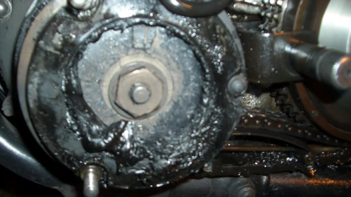
He then stripped the primary drive to get to change it, damaged the crankcase with the sprocket puller (screwed the bolts in too far) , forgot or didn't bother to clean the gasket faces, consequently the case didn't sit flat and hence the stator touching.
 
Looking at the picture in post #42 , the top two mounting holes in the stator do not line up with the outrigger plate . Nothing to do with how it is mounted to the bike . You would see the same if it were sitting on a bench .
 
A disappointing update guys. I got the stator and rotor to a tight .3mm clearance all the way around, buttoned everything up and took it for a test ride. I noticed the ignition warning light come on, got it home, and pulled off the primary cover to check on things and the stator was torn up again. Maybe I needed to really wrench down the nuts on the studs I had shaved, I used locktite and spec torque. The primary is now completely stripped down (FWIW there was nothing wrong with the faces or gasket between the motor and inner primary) and now I'm back to cleaning out an explosion of plastic shrapnel and tallying a list of replacement parts. There was enough heat buildup that the rotor nut and last ~1" of crankshaft has taken a golden hue. I have no idea what to do next. I'm very disheartened. :(
 
Better check your crank again and check that the rotor is not moving on the shaft. 0.008" (or even 0.007") works on all Lucas alternator equipped bikes and you had 0.011"!
 
That's really too bad! Most frustrating, Anvill.

Going into my personal way-back machine, I have a vague recollection of a Lucas alternator in the Display-of-Disasters Showcase at Pokes where I worked in the 90s. Said rotor, out of an Atlas or early Commando, I believe, had the magnets standing proud of the rotor casting. The first symptom was that, along with some nasty noises, the wires to the alternator had been sucked into the primary case. On disassembly, the studs were sheared and the rotor had gripped the stator and spun it around. The usual failure was that the hub would come loose from the rest of the rotor and begin a knocking sound. I suppose you'd have noticed if the magnets were loose from the casting. I know it's a long shot but could the magnets somehow contact the stator only at high RPM? Perhaps you have a faulty rotor.

I had bad dreams about this sort of thing last week when I reassembled my Matchless primary who's stator resides in the outer primary cover so unless I'm missing something, there's no way to check it on reassembly. That said, the Matchless rotor looks different from the Commando rotors. Perhaps smaller by a few thou?
 
A lot of good experienced advise being given here.

Maybe you've done all this but this, I would pull everything apart.
I would try everything possible to align the inner primary.
1. I would strip the entire primary, pull the inner cover.
2. Remove center bolt.
3. Refit inner primary without center bolt.
4. Fit rotor with no key, fit outrigger and stater.
Take whatever steps necessary to fiddle, work, manipulate the inner for alignment.
Once aligned, measure stud distance and reset accordingly.
I would also be checking trans alignment during this....
Everything is apart and cleaned. When I do get back to this I will put full sized studs back in and try fitting without the center bolt. It will take a while for the parts to come in and perhaps a while longer to lick the wounds. All part of having vintage vehicles. Does everyone use the four fiddly little bending lock washers to fasten the outrigger plate or is it safe to try something more amenable to repeated refitting? I'm getting tired of those things.

Incidentally does anyone know of any reputable Norton mechanics in the central Texas area? I'm really hoping not to go that route but its a good thing to have in the back pocket and at a certain point it will be cheaper than endlessly buying stators...

Thanks,
Anthony
 
Obviously, when the bike was new, the problem didn't exist or the bike would not have been usable. So...what has changed? Seems that either the crankshaft nose would have had to warp/be bent OR the aftermarket components are at fault. A crankshaft bending/warping seems unlikely to me but, then again, since the crankshaft halves are bolted together, :eek: who knows...

Have you tried an OEM Lucas rotor/stator to see if sufficient clearance to avoid contact can be obtained? Maybe the aftermarket parts are not the same dimensions as the OEMs. If there is a difference, perhaps OEM components would ensure no contact and sufficient power, even if they have a larger gap all the way round. If so, that would at least be good info.
 
Last edited:
The usual failure was that the hub would come loose from the rest of the rotor and begin a knocking sound. I suppose you'd have noticed if the magnets were loose from the casting. I know it's a long shot but could the magnets somehow contact the stator only at high RPM? Perhaps you have a faulty rotor.

There are both Lucas and Wassell rotors in Anvill's pictures.
I don't know if the Lucas 54201143 rotor was one of the easily self-destructing types or a (supposedly!) 'welded' rotor (my Mk3's rotor is also 54201143) as only the 54202298/9 rotors are known to be the safer 'welded' type (although it appears they are not actually welded).

The latest red/green box 'Lucas' (also Wassell as they have the rights to use the Classic Lucas trademark) rotors are supposed to have magnets keyed to the core but an example of exactly how this is done has yet to be seen.


I suppose you'd have noticed if the magnets were loose from the casting. I know it's a long shot but could the magnets somehow contact the stator only at high RPM?

Not the actual "magnets" as they are covered by laminated caps with lugs that lock the magnets to the rotor casting.


The Wassell rotors can be oversize.
 
The link to the "alternator issues" is very good reading. I found the following statements to be very interesting:


"The original design of the Lucas Rotor and Stator was for an outside diameter of 74mm on the rotor, and an inside diameter of 75mm for the stator (those numbers were given to me by LAP)

This would give you 0.5mm air gap all around – so comfortably exceeding the minimum that Lucas originally specified back in the day.

I have seen closer to 5 thou (0.127mm) on brand new Wassell/Lucas kit fresh out of the box – way tighter than I am comfortable with."


And:

"A factory standard charging system is on a bike and is problem free for over forty years, then just after an owner upgrades to a new reg/rec, I shortly after get to hear about electrical problems and charging related issues.

This is a pattern I am seeing time and time again."
 
Need to remember that in post #1, he shows a Wassell rotor and a new 3-phase stator - Wassell or Lucas? In post #1 he clearly has enough clearance, just not centered correctly. Then when he does manage to get it to have 0.011"clearance (more than enough) he goes for a ride and gets the rotor so hot that is discolors the crankshaft end and melts the stator. We assume that the rotor was rubbing on the stator, but that hasn't been shown or stated. A picture of the damage to the rotor and stator would be helpful. With the rotor getting that hot, it's most likely no good now - magnets and high heat do not go well together.

The Wassell branded parts, in general, are not the same as the current, red-box Lucas parts even though Wassell owns/has them made. Mostly the older Lucas green-parts are good too but I'm less sure of them "across the board". For instance, the first green-box headlight warning lights were junk, but the later green-box and the red-box are good. The non-Lucas headlight shells Wassell sold a few years ago were junk, but the green-box and red-box are better than OEM, IMHO. I've used the current Lucas rotors with OEM and Lucas stators without trouble, and I've used the Lucas stators with OEM rotors without trouble. Most often I use Lucas rotors with OEM stators because I often come across OEM rotors with the center loose. Anyone whose found better should let us know!
 
FWIW - I was brought a BSA A50 this week that the owner was having trouble fitting a new Lucas stator to. I measured the OEM and new stator - both measured identically to within a thou on all the critical interfaces. When I offered it up to the bike, it fit perfectly - the rotor and stator were very well centered, with lots of clearance.

I am not sure what the owner's issue was, but he was happy that I was able to make it work...

+1 for new Lucas brand parts being a one for one match to the OEM components.
 
I have the same issue on my MK3, I set up the locating mount on the mill after removing the studs and took 10 thou off the locators with my boring head. The location fit was tight as hell anyway. I was also going to bore the holes out some, but it seemed to do the trick so I left it.
 
The last 3 Brits of mine I’ve fiddled with I had the rotors turned down to give 0.020” clearance, ie .040” undersize.
I haven’t done any clever measuring of output, but can say that they all work just fine.
 
If you recall, Superblend mains were first installed on Combat motors to "combat" bearing failure from crank flex. How much did they flex? I don't know. Nor do I remember if we replaced more alternator rotors on combat motors but I replaced tens of failed rotors over the years. Many of them had worn keyways so the rotor could knock back an forth on the key. Was that the cause of the failure or did the failure somehow wear the keyway after the hub came loose? On my Matchless the rotor keyway is worn and the rotor turns freely on the crank with no key. Last time I had it apart I had reassembled it with green loctite (I don't remember doing this but I had to use a three-jaw puller to get it off). I reassembled it with green locktite. There has been no hint of failure in many thousands of miles. I had pulled it apart to fix an oil leak. This may be a bit of a birdwalk but there has to be some reason for interference under load at RPM which isn't evident when static. I would bet on crank flex and close clearance combined as the source of the problem. I know MKIII cases had some material removed below the camshaft compared to previous cases could that contribute to the cases allowing more crank flex?

It's been a long time that I haven't kept up with new developments and I'm working off old memory, so please bear with me if I'm going over ground that's been discussed before.
 
If you recall, Superblend mains were first installed on Combat motors to "combat" bearing failure from crank flex.

However, the factory only began fitting the (R&M/RHP 6/MRJA30, later FAG NJ306E) 'Superblends' after the Combat series had ended.
 
Exacting alignment of one component to another is often accomplished with offset studs and dowels or a combination of both.
I used them when exact centering of a bell housing to an output shaft was required when aligning high performance engines to transmissions.
Its the same principle/requirement regarding centering/alignment and you can access almost any configuration of offset fastener your needs require, be it the carrier or the stator itself.
The photo below is an example of the offset design and is just one of hundreds of configurations available for an offset fastener.

866202360_kHNx2-L-4022096749 (2) .jpg
 
Last edited:
Nigel, The nuts with under sized heads you refer to are standard aviation items. See

MS 21042 Stop nuts aka Jet nuts

For the stator studs, MS 21042-5 would be the correct size. FYI, these are available with both under sized 6 & 12 point heads.
While rummaging around through my aircraft hardware collection [several hundred pounds worth] I found another aircraft nut which would also work for retaining the alternator stator. It's AN365-524. It's a Nyloc nut with a 7/16" hex head, rather than the standard 1/2" hex head on common hardware. See

Aircraft Spruce AN365 Nyloc Nuts

This might be a better choice. The MS 21042 nuts are an "all steel" [more torque required to break the nut free from it's stud] lock nut, so might be more likely for the entire stud/nut to come loose from the engine.
 
Wow - first time I've known the start of an urban legend - interesting how something can work on lots of bikes for over 40 years and now won't :)

At first, I thought it would be specific to the MKIII, but now it's growing to all Commandos!

BTW, we still don't know what actually happened either time!
 
Given that the bike had many miles on it before I got it, I’m confident the mistake was on my end somewhere. I pulled and replaced the motor and tranny in the frame and rebuilt the primary myself, so I must have done something wrong to create that pinch. I now have primary pulled and the gear box and inner primary stud loose on their bolts, and I will carefully build it up from square one with no modified parts. Starting from this point I hope to be able to get it there. In researching my issue I saw several mentions of this pinch area being a common mkiii problem but perhaps it’s just a matter of rebuilding from scratch to get it right.

I was surprised to see how much wiggle the inner primary case allows with everything loose. Doing my best to keep the main shaft also aligned in its oil seal will be a part of the equation as I try again.

In each case it appeared the rotor made contact with the stator or at least heated enough to melt the stator potting material. Both times there was no scraped metal on the rotor or stator but the potting material had badly melted and slung molten plastic bits all inside the primary case as well as coated and caked onto the rotor. I’ll try to take pics this evening.

Anthony
 
Status
Not open for further replies.
Back
Top