Uh-oh!

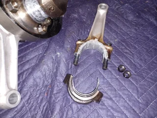
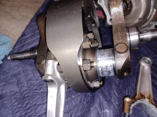
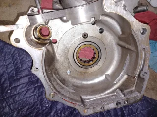
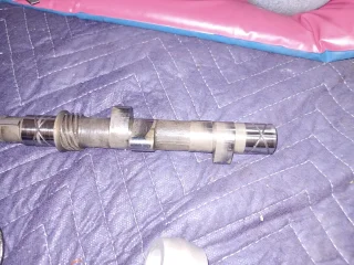
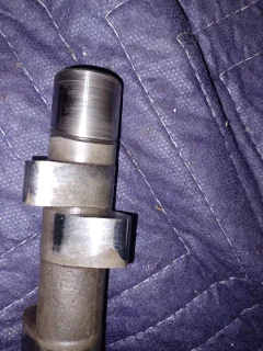
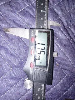
Split the cases today. The hardest part was removing the worm gear from the crankshaft, I used a 1/2 in. drive ratchet and 2 ft. cheater bar. The pictures speak for themselves. The timing side journal looks to be glazed with aluminum from the conrod. It looks like an aluminum glitter bomb went off in the engine! What's my next step? Measurement is of the big end journal.
 

Attachments

  • Uh-oh!
    20230810_185905.webp
    563 KB · Views: 417
  • Uh-oh!
    20230810_185914.webp
    316.3 KB · Views: 400
  • Uh-oh!
    20230810_185943.webp
    556.5 KB · Views: 377
  • Uh-oh!
    20230810_190055.webp
    523.2 KB · Views: 335
  • Uh-oh!
    20230810_190903.webp
    355.8 KB · Views: 330
  • Uh-oh!
    20230810_190827.webp
    585.4 KB · Views: 311
  • Uh-oh!
    20230810_200026.webp
    644.6 KB · Views: 381
Wow, you really are lucky, you were seconds away from a hand grenade job !

Sadly, I reckon it’ll be very difficult indeed to separate cause from effect and identify what the root cause was. So going through everything to clean, inspect, measure, is your only real option.

I also think you’ll be lucky with the crank too, most damage appears to be deposits rather than removed metal. I reckon you’ll get away with a re grind.


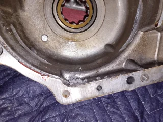
Not sure how deep those gouges in the case are. If not too deep I’d smooth them out to remove stress risers. If too deep for that, they should be filled in with weld before smoothing. Might sound scary but it’s not a big job at all for a competent welder.

Other than that is ‘just’ straightforward rebuild time, starting with a very careful strip and absolutely thorough clean, of everything, inc the inside of the crank, oil pump, all oil ways AND the oil tank, etc. EVERYTHING.

Its just up to you to decide whether to build back as is, or build back better.
 
Last edited:
The evidence looks to be destroyed but some extra info could give some clues but any analysis cannot be 100%.

Are the 2 shells in the photo shown where you found them.

How tight were the big end nuts on the bolts.
 
"Sadly, I reckon it’ll be very difficult indeed to separate cause from effect and identify what the root cause was."


Hydrodynamic bearing. It is crystal clear there was an oil starvation/contamination event, somewhere along it's life.
In some instances, the damage is minimal, but the longevity is compromised.
Now, that oil starvation may have been cause by the recent con rod being mangled out of shape by the manifold bolt disaster, but that was what led to oil starvation.
As I mentioned before, you were smart to shut it down. So many others run them to the "BANG!"
Regrind the crank, thoroughly inspect/repair the oil supply system. It will run, and last as it was designed.
Personal choice, I chose to install a new oil pump when I rebuilt the lower end.
 
Last edited:
I'd guess splitting the crankshaft (making a note of which way the flywheel is oriented) would be next to see if the oil holes are blocked.
Measuring how far that stud protrudes might be first, before undoing it. Even to eliminate it.

It just looks wrong. But it might help if we also saw the other (drive side) end of the stud, I feel it most likely doesn't protrude through the nut.
 
Split the cases today. The hardest part was removing the worm gear from the crankshaft, I used a 1/2 in. drive ratchet and 2 ft. cheater bar. The pictures speak for themselves. The timing side journal looks to be glazed with aluminum from the conrod. It looks like an aluminum glitter bomb went off in the engine! What's my next step? Measurement is of the big end journal.
1st job, screw that stuffed conrod on the wall. 🙂
 
Jep, looks very similar to the Trident I bought years ago. Here, one circle had opened up and scored the bore on the same cylinder. Always wondered if the two failures were connected.
I ended up getting a new rod, crank regrind, rebore and pistons. Everything else was OK.
 
I'd guess splitting the crankshaft (making a note of which way the flywheel is oriented) would be next to see if the oil holes are blocked.
Larry, please report back on your findings of deposits.
From the photo it looks like the top crank bolt has been rubbing on the rod. It apears to be sticking out over the journal.
I noticed that too. I guess someone (probably an amateur) split the crank in the past. If the crank is rebuildable (not bent, and journals not deeply scored), I'd replace all crankshaft bolts if I were you.
After an incident like this, the present state of bolts is unknown, and who knows which bolts were used when the PO worked on it.

Out of interest, is the offending conrod compressed only, or is it noticeably bent as well? Are scoring marks visible from the protruding crankshaft bolts?

- Knut
 
How would any sludge break away? It's being constantly held in place by the centrifugal forces generated by the crank rotation.
That's a big *perhaps*. At 12 o'clock (that's at the radial throw) maybe, but not a 3 and 9 o'clock. The possible occurence of sludge breaking away raises the question, how wise the use of a sludge trap is, provided a proper oil filtration is in place externally.
Location of the "sludge trap" / oil reservoir is worth considering for anyone planning a billet crankshaft .....

- Knut
I doubt the sludge trap had anything to do with it. If sludge traps were or wet sumping (for that matter) were an issue, thousands of Norton twins would have blown up. Question???? Has anyone seen a sludge trap in a Commando filled to the point of blocking the oil holes and starving the rods???
 
The evidence looks to be destroyed but some extra info could give some clues but any analysis cannot be 100%.

Are the 2 shells in the photo shown where you found them.

How tight were the big end nuts on the bolts.
The two shells were found just as the photos show. The big end nuts were not even finger tight. I figure another couple minutes running and the connecting rod would have blown through the case.
 
This is the timing side con rod that went, the sludge is held in the centre flywheel after the oil has passed through the timing side, any loose sludge or a blocked sludge trap would starve the driveside not the timing side.
True, but is it consistent with observations that the reservoirs within journals are completely free of any sludge? It's been too long since I split a pre-Commando crankshaft, The Mk'3 crankshaft I dismantled last had no discernible sludge, but hadn't run very far.
Flow of oil is low, thus no flushing effect right to left. Journal lube holes are located 90 degrees to the radial throw mainly to limit centrifugal pressure, but I think the location was selected also in part to avoid deposits to escape freely.

- Knut
 
Last edited:
The two shells were found just as the photos show. The big end nuts were not even finger tight. I figure another couple minutes running and the connecting rod would have blown through the case.
That is pointing to oil starvation, the shells seize on the journal unseize and reseize and the clearance opens up, the gap creates a pounding action so the nuts come loose. Gap opens even more allowing the shells to rotate. Caught just before the bottom of the con rod came loose and crankcases split. The flywheel bolts are odd but until the con rod started moving around they probably just cleared it, once the rod was free to wander they made contact.

So where did the oil starvation come from, why the timing side before the driveside when its normally the driveside that goes first. Was the clearance or strength of the timing side shells compromised by the previous problem of the valve hitting the piston.
 
Last edited:
Kommando said
Was the clearance or strength of the timing side shells compromised by the previous problem of the valve hitting the piston. 👍
 
Back
Top