Labled Wiring Harness

Status
Not open for further replies.
Joined
Sep 4, 2009
Messages
106
Country flag
Has anyone on this forum ever posted a diagram of a labled wiring harness? Particularly the '72-'73 model year.

Like this one for the earlier models:
Labled Wiring Harness


I have the wiring diagram, which is great, except that there are some un-connected terminals, and a few cut wires on my otherwise decent wiring harness.

It would be handier to look at a labled harness than try to sosrt through the wiring diagram with a test light and volt meter.

Labled Wiring Harness

Labled Wiring Harness
 
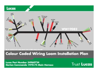
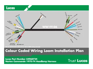
If you get the Wassel/Lucas part number for the harness you need the diagram of and then do a Google image search it will get you the equivalent diagram. Just watch out as they have errors. I would do it but not on my pc.
 

Attachments

  • Labled Wiring Harness
    Main-Harness-70-74.webp
    38.4 KB · Views: 2,174
  • Labled Wiring Harness
    Headlamp-Harness-70-74.webp
    37.4 KB · Views: 2,431
BrianG said:
I have the wiring diagram, which is great, except that there are some un-connected terminals, and a few cut wires on my otherwise decent wiring harness.

As it has electronic ignition, then all the original white/purple and certain black/white 'BW' and black/yellow 'BY' ignition wires must remain disconnected. White/blue WU can be used as the feed for electronic ignition but if possible connect the Boyer box negative directly to the WY from the kill button and completely disconnect WU.
Various other spare wires are for the Interpol model.

Although white/purple or 'WP' isn't marked on the original factory wiring diagram, it's the section between the ballast resistor and both coil negative terminals of the original points ignition.
You won't find WP on the Wassell Lucas 54960724 diagram either, or in their harness, as they use WY instead of WP so with the original points ignition WY from the kill button connects to WU which goes to the ballast resistor then reverts back to WY. :roll:
The two wires on that diagram marked as "Warning Light Assimilator" are for the accessory socket and the three marked "Blue Lamp Flasher Unit" are the actual assimilator wires. :? :roll:

You may also find a WP, also a WR (from the switch cluster push button) running back to the battery compartment, those wires are also unused and not shown on any diagram, the WR drawn no further than the main connection point but if the WR is there then make sure the terminal can't short, or disconnect WR at the main connection point below the fuel tank.
 
If you remove the stuff in a Commando electrical system that you don't really need, capacitor, rear brake light switch, warning light assimilator, ballast resistor to think of a few. and fit a decent regulator rectifier, electronic ignition, a couple of headlight relays. Half of your wires would be redundant.
 
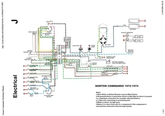
I got this from another member here. It has been helpful a number of times. I haven't seen the original poster of this around, I don't know if he is still in the saddle or not. I have it on my computer in a larger format but I can't post it here.


Maybe this will work better, if you click on it, it will open in a new window:


Labled Wiring Harness
 

Attachments

  • Labled Wiring Harness
    Commando Wiring.small scale.webp
    34.2 KB · Views: 2,664
Status
Not open for further replies.
Back
Top