
You are using an out of date browser. It may not display this or other websites correctly.
You should upgrade or use an alternative browser.
You should upgrade or use an alternative browser.
Wiring a solid state rectifier
- Thread starter ELLIS
- Start date
- Status
- Not open for further replies.
texasSlick
VIP MEMBER
- Joined
- Jan 2, 2013
- Messages
- 4,164
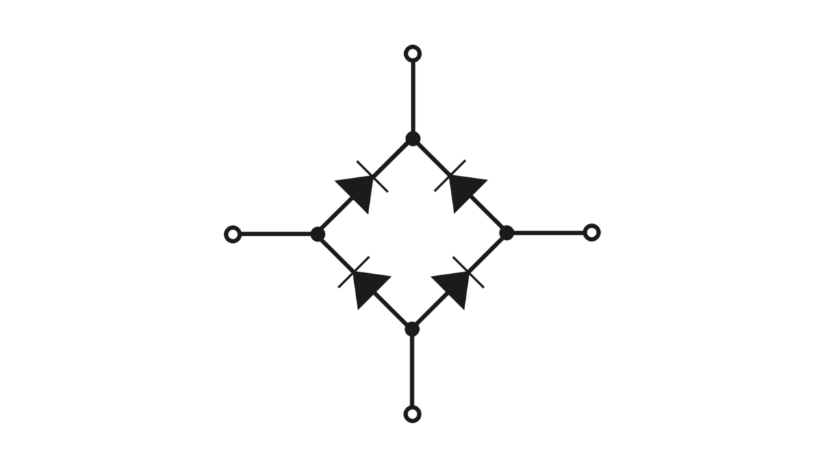
Your solid state rectifier should have two terminals marked with the "cycle" symbol which looks like a wavy line. These are the alternator, or AC inputs. It does not matter which of the stator leads goes where on these two.
The other two terminals should be marked one with a +, and one with a -.
If your bike is positive earth, connect the plus (+) to earth, and the minus (-) must find its way to the battery neg. via your bikes usual wiring. Sorry, can't be more specific without knowing your bike.
Similarly, with a negative earth bike, connect the minus to earth, and the plus to the battery positive terminal.
There are NO unused terminals on your rectifier. If your old rectifier has only 3 wires, it is because the rectifier is earthing via the mounting bolt.
Slick
Last edited:
guest76
Guest
- Joined
- Nov 5, 2012
- Messages
- 1,034
@Craig not sure I’m the man, but thanks anyway LOL
@ELLIS the MK3 had a half wave rectifier, and relied on two zener diodes to do the rest of the rectification.
...actually it was not a particularly good idea, but it was the only way Lucas could think of dealing with a higher output alternator stator.
You can wire in a full wave rectifier with no problem - and the only difference is the connection to earth.
Although this page is all about testing your rectifier, it shows clear pictures of the pins and where they need to go for the different types of rectifier available:
 granttiller.com
This picture shows a MK3 with half wave rectifier and a pre-MK3 with full wave rectifier sat side by side - it may be useful.

Shout if you’re stuck.
EDIT: This picture shows the full wave rectifier in place of the original half wave rectifier on a MK3 together with an illustration of how to connect it up.
There is no reason not to use the full wave bridge, so I would recommend grounding the positive side as shown.

@ELLIS the MK3 had a half wave rectifier, and relied on two zener diodes to do the rest of the rectification.
...actually it was not a particularly good idea, but it was the only way Lucas could think of dealing with a higher output alternator stator.
You can wire in a full wave rectifier with no problem - and the only difference is the connection to earth.
Although this page is all about testing your rectifier, it shows clear pictures of the pins and where they need to go for the different types of rectifier available:
Grant Tiller | Testing your Motorcycle Rectifier
A Rectifier is the part of the charging system that convert the AC voltage from the alternator into DC voltage which can be used to charge the battery. Here is a picture of a Lucas alternator rotor (the magnetic bit in the middle) and stator (the bit round the outside with the wires coming out of
This picture shows a MK3 with half wave rectifier and a pre-MK3 with full wave rectifier sat side by side - it may be useful.
Shout if you’re stuck.
EDIT: This picture shows the full wave rectifier in place of the original half wave rectifier on a MK3 together with an illustration of how to connect it up.
There is no reason not to use the full wave bridge, so I would recommend grounding the positive side as shown.
Last edited:
- Joined
- Dec 8, 2011
- Messages
- 404
I assume that you are using an aftermarket rectifier. To hook it up to a Mark III Commando
Peter Joe
- Hook up your alternator green/yellow and green/white wires to the two rectifier terminals marked AC (Alternating Current)
- Hook your brown/blue wire to the negative terminal of the rectifier
- The positive terminal that normally goes to ground on the rectifier will not be used. You can cover that terminal so that it cannot accidentally connect to ground.
Peter Joe
Last edited:
- Joined
- May 5, 2017
- Messages
- 657
Ellis,
I'm not Grant [gtiller], the two Zener diodes on the Mk III do double duty. They act as the other two diodes for the rectifier, [thus making it full wave] and regulate the voltage. The older RM 19 & 21 alternators are 120 watt [10 amp] units. A single Zener can handle that. The RM 23 in the Mk III is a 180 watt [15 amp, also listed as 14.5 amp] unit. The extra output requires the two Zeners to handle the voltage control at high RPMs. It's actually a very clever design.
Charlie K
PS If you buy one of the aftermarket full wave rectifiers, on a Mk III, you will only use half of it. The other two diodes will be your "back up". If you blow out the two diodes in use, just switch the stator wires to the unused diodes and keep on truckin'
guest76
Guest
- Joined
- Nov 5, 2012
- Messages
- 1,034
@ELLIS if you have a full wave rectifier sat there on your bike, for the sake of connecting the fourth pin to earth, you may as well use it.
When you are relying on the zeners as half of your rectification circuit (ie converting AC to DC) it means that if you lose a zener due to a dirty connection, or component failure, you will also lose half of the power coming out of your alternator.
The new full wave encapsulated rectifiers are more reliable and on our Commandos are safely tucked away from muck and road grime, hence my recommendation to connect it as a full wave bridge.
- Joined
- Jan 6, 2017
- Messages
- 115
Thanks gtiller i will add that earth today. I run led lights and wondering if thats the cause of the ignition warning light to stay on up to 3k rpm before it starts to fliker and go out. Does the alternater need to work harder generating more power maybe with incandesent bulbs.
ELLIS
ELLIS
guest76
Guest
- Joined
- Nov 5, 2012
- Messages
- 1,034
The warning light assimilator on the MK3 is a little better than the terrible 3AW 3 wire ‘silver can’ assimilator on the older bikes.
The MK3 one at least is solid state and takes both sides of the AC rather than just one leg.
They don’t last forever, and it is possible that it’s failing, although they are twice as resilient as the 3AW (maybe it will last 50 years instead of 25 years)
Just like the older assimilator though, it is still looking at AC, so you are ‘monitoring’ what is coming out of the alternator in AC, not at what is being rectified in DC.
Your LED lighting shouldn’t make a difference to when the red light goes out - typically it will flicker on at idle, and go out as soon as you blip the throttle with all your lights off.

If it is still misbehaving, check that both sides of the alternator are connected to it properly - maybe one of the connectors (either at the assimilator itself, or further up the line to the alternator) is loose or dirty.
It would come on later if it’s seeing less from the stator.
The MK3 one at least is solid state and takes both sides of the AC rather than just one leg.
They don’t last forever, and it is possible that it’s failing, although they are twice as resilient as the 3AW (maybe it will last 50 years instead of 25 years)
Just like the older assimilator though, it is still looking at AC, so you are ‘monitoring’ what is coming out of the alternator in AC, not at what is being rectified in DC.
Your LED lighting shouldn’t make a difference to when the red light goes out - typically it will flicker on at idle, and go out as soon as you blip the throttle with all your lights off.
If it is still misbehaving, check that both sides of the alternator are connected to it properly - maybe one of the connectors (either at the assimilator itself, or further up the line to the alternator) is loose or dirty.
It would come on later if it’s seeing less from the stator.
- Joined
- Nov 20, 2004
- Messages
- 20,082
If you buy one of the aftermarket full wave rectifiers, on a Mk III, you will only use half of it. The other two diodes will be your "back up". If you blow out the two diodes in use, just switch the stator wires to the unused diodes and keep on truckin'
The aftermarket full-wave rectifiers normally have two AC terminals so how would you switch the stator wires to the unused diodes?
The warning light assimilator on the MK3 is a little better than the terrible 3AW 3 wire ‘silver can’ assimilator on the older bikes.
The MK3 one at least is solid state and takes both sides of the AC rather than just one leg.
Although as you know, early Mk3s still had the 3AW silver can assimilator.
Last edited:
maylar
VIP MEMBER
- Joined
- May 13, 2007
- Messages
- 4,213
You might also get a few tenths of a volt more DC. I'd have to check the specs to be sure, but I believe the forward voltage drop of a typical zener is higher than a typical rectifier diode.When you are relying on the zeners as half of your rectification circuit (ie converting AC to DC) it means that if you lose a zener due to a dirty connection, or component failure, you will also lose half of the power coming out of your alternator.
guest76
Guest
- Joined
- Nov 5, 2012
- Messages
- 1,034
@maylar you are totally right, but you’d only get more volts if you reconfigure the Zener wiring.
I decided not to suggest that Ellis did this in favour of keeping any changes to his bike at the bare minimum and things nice and simple for him.
...plus you'd be right on the edge of the current handling capabilities of the factory Zener - don't forget the MK3 has a higher output RM23.
But yes, if you did move the zeners to the DC side, theoretically you’d get around the 0.7 volt drop issue that you see on the MK3 versus the pre-MK3 charging system.
Last edited:
- Joined
- May 5, 2017
- Messages
- 657
Thanks gtiller i will add that earth today. I run led lights and wondering if that's the cause of the ignition warning light to stay on up to 3k rpm before it starts to flicker and go out. Does the alternator need to work harder generating more power maybe with incandescent bulbs.
ELLIS
It seems that a lot of Brit bike owners [as well as some vintage smaller Asian bikes] think that their Norton, BSA, Triumph, etc. has an alternator that functions like the one in their car. It doesn't. All alternators generate electricity by moving a magnet past coils of wire. Your car & most modern motorcycles have a true alternator. It's rotor [the center part that spins] is an electro-magnet. That means that you have to feed electricity into it, to generate a magnetic field, which then produces more electricity in the stator [the stationary part] as the rotor spins. On Lucas motorcycle systems since aprox 1970, the stator is the part encapsulated in epoxy with wires coming out.
Your car's voltage regulator controls the amount of electricity going INTO the rotor. If the system voltage starts to go to high, the voltage regulator throttles down the amount of voltage going into the rotor. That creates a weaker electro-magnetic field [weaker magnet], hence, less power produced in the stator. When more power is needed [system voltage dropping to low], the voltage regulator increases the power going into the rotor. This makes a stronger electro-magnetic field [stronger magnet]. That stronger magnetic field in the rotor will create more power in the stator. As your car's engine speed varies, or you turn on or off electrical loads [lights, A/C, heater, heated seats & glass, etc] the voltage regulator can compensate by varying the strength of the magnetic field of the rotor.
Our Nortons use what is more properly termed a dynamo. That is because it uses a rotor with permanent magnets. That means that you can not control the rotor's magnetic field's strength, via a voltage regulator, like you do in a true alternator [your car or truck]. The faster you spin the rotor on a dynamo, the more power is produced in the stator [output power].
Since you can't throttle a dynamo's output at the rotor [fixed strength of the magnetic field], you have to find another way to limit the voltage [15 volts max] in the system.
A battery that is not fully charged will use some of the systems' output, to charge itself. The ignition coils & lights will also use some. When the dynamo is generating more power, and therefore higher voltage [high RPM operation] it's possible it will create more power than we need. This situation can occur during conditions where the dynamo is producing more power than we need, such as high engine RPM, with a fully charged battery or turning off your lights. We need a way to absorb the excess that is generated.
Diodes are the electrical equivalent of a one way valve in a hydraulic system, like your home's plumbing system. It lets electricity flow in one direction, but not the other. That's how a diode bridge rectifier works, to turn AC voltage [what alternators & dynamos create] into DC voltage. Our light bulbs don't care if we feed them AC or DC. However, our ignition coils and battery do! Feed AC into a battery and it will die in a few weeks/months.
A Zener diode is a special type of diode. During normal operation, when system voltage is below a designed voltage, for us about 14 volts, it does nothing. It's basically an open circuit [a light bulb that's turned off]. As the system voltage increases above 13.5 volts, it starts to allow electrical current flow in the opposite direction. This causes it to become a load on the system, like a light bulb. It absorbs the excess power to keep the system voltage from going to high. Think of the Zener diode like a powerful light bulb controlled by a rheostat, like dim-able home lighting. It's "dimmer" is voltage sensitive. As system voltage rises towards desired limits, it acts like a dim-able light bulb getting brighter and using more power. The Zener will absorb power as needed to keep the system voltage within the desired limits [15 volts max]. The power it absorbs is disapated as heat. That is why it's mounted in a large chunk of aluminum [your Z plates]. The Z plate acts as a heat sink, shedding that heat, so that the Zener does not fail, due to over heating. This is how a Zener diode(s) control the system voltage in a dynamo charging system, like the Lucas units fitted to our bikes. The downside of a dynamo system, is that at low engine RPM, with the lights on, it may not create enough elecricity to power the lights and charge the battery. This usually happens as the rotor's magnets weaken with age. Using high powered Halogen headlamps makes this situation worse, if you have weak magnets in your rotor.
Grant [gtiller] is correct that the Lucas RM 23 [180 watt] system in the Mk III will lose half it's charging power if one Zener diode fails. Using a full wave [4 diode] bridge rectifier on an RM 23 system , if a diode fails in the rectifier, you only lose 1/4 of the output, per failed rectifier diode. So, using one does offer a benefit. The earlier RM 19 & 21 [120 watt] systems [750 & Mk II Commandos] come with a full wave rectifier, so the above diode failure analysis also holds true, for them. In these systems, a failed Zener diode will usually [not always] cause an over charging situation, because it can not absorb any power. If their Zener fails "shorted", it acts like you have an extra headlamp on high beam, dragging the charging system voltage down, resulting in a low or dead battery.
I hope this helps you understand your charging system a bit better.
Charlie K
Last edited:
- Joined
- Jan 6, 2017
- Messages
- 115
chaztuna
Your post was indeed very easy to understand and it gives an amature like me a chance to understand the charging system. At the moment i am going through the earth connections making shure they are all clean and doing their job. I think the next job is to checkout the Zener diodes to see if i have a faulty one. Tomorrow i should have two members of our VMCC club comming round to give me some help hopefully. I will post again when we have found the fault.
Cheers
ELLIS
- Joined
- Feb 10, 2009
- Messages
- 2,840
chaztuna said:Our Nortons use what is more properly termed a dynamo.
Dynamo usually means a direct current generator with a commutator.
- Joined
- Jun 25, 2004
- Messages
- 929
Our Nortons use what is more properly termed a dynamo.
Excellent description and on the mark. Thanks Chaz for taking the time to write this.
Like pointed out above, the type of alternator that our bikes use (permanent magnet) is actually technically called a magneto - although our in our current vernacular, the term magneto has been associated with a far more complex device (that does happen to contain a magneto -
") ) .
) .- Joined
- Nov 20, 2004
- Messages
- 20,082
I think the next job is to checkout the Zener diodes to see if i have a faulty one.
As it's the 850 Mk3 charging system the two Zeners are connected to the stator output wires (GY & WG) not the 'fused' negative (NU).
- Joined
- Apr 20, 2011
- Messages
- 5,773
Can't agree with chaztuna description of an alternator being a dynamo, this is trying to re invent the dynamo word, which will ultimately confuse everybody!!!!!!Dynamo usually means a direct current generator with a commutator.
- Joined
- May 5, 2017
- Messages
- 657
Thanks guys for calling me out. You are indeed correct. In my head, I hear the voice of "Auggie Doggie" saying "Oh, the shame of it all"!Excellent description and on the mark. Thanks Chaz for taking the time to write this.
Like pointed out above, the type of alternator that our bikes use (permanent magnet) is actually technically called a magneto - although our in our current vernacular, the term magneto has been associated with a far more complex device (that does happen to contain a magneto -
Charlie
- Status
- Not open for further replies.