Early camshaft

Status
Not open for further replies.
Bernhard said:
Re; I wouldn't.
You'd lose 1000 revs. And the cam followers may not be suitable.
And if it damages something, it could get very expensive - for something that doesn't cost that much to have the right one...

Rohan is never wrong :!:
Re; “You'd lose 1000 revs. And the cam followers may not be suitable”
Don’t know where you get this from :!:

Again, don't know where this old thread revived from,
but early dommie cams were only good for 6000 rpms and maybe a bit more.
A Commando with a 7000 redline would be a bit revless ?!

And the cam followers were ground differently in a Commando to early dommies.
Unfortunately DynoDaves cam survey used his own system of degreeing a cam,
without using the appropriate Norton cam followers.
So don't really show what lift or curve was applied to the valves in a running Norton engine.
 
Rohan said:
And the cam followers were ground differently in a Commando to early dommies.
Unfortunately DynoDaves cam survey used his own system of degreeing a cam,
without using the appropriate Norton cam followers.
So don't really show what lift or curve was applied to the valves in a running Norton engine.

How did the Dommie lifter vary from the flat tappet employed in a CDO?

I think DynoDaves cam measuring method is appropriate and very similar to the way most of us would measure a cam. He used a flat lifter for the flat tappet cams and a radiused follower of appropriate curvature for cams specified to run with such a lifter, to generate data sets of cam lift vs duration. His data sets are readily converted to valve lift by multiplying his cam lift data set by the rocker ratio of 1.13. The majority of cam data posted on this site over the years has been in cam lift not valve lift, e.g, Comnoz and jseng1 cam data postings are almost without exception in cam lift.
 
Commando cam followers have different part numbers to dommie ones. (?).
Maybe someone can say what the difference is.

You can't measure the lift at the valves against degrees either, and then calculate back to figure out what cam you have,
from published cam diagrams.
 
I thought this was interesting, on Jim Schmidts website.

Jim Schmidt shows his special lightweight radiused lifters for Nortons.

Early camshaft

Early camshaft


"Weighing approx 1/2 as much as original Norton flat lifters, JS Motorsport's radiused lifters make your Norton more free reving while reducing stress, friction, wear and overheating of the valve train. Reducing the weight enables your valve train to operate more acurately and efficiently. Pushrod and rocker arm flex is minimized allowing the full lift your cam was designed to deliver and allowing use of more aggressive profiles than would normally be available on cams designed for heavy inefficient stock Norton lifters. Expect greater relibility and longer service."

we diverge a bit....
 
WZ507 said:
The majority of cam data posted on this site over the years has been in cam lift not valve lift, e.g, Comnoz and jseng1 cam data postings are almost without exception in cam lift.

That is peculiar, is it not ??
Its the valve lift that is ultimately the important bit.....
 
Rohan said:
You can't measure the lift at the valves against degrees either, and then calculate back to figure out what cam you have,
from published cam diagrams.

Sure you can. If you have a data set given in valve lift it is converted to cam lift by applying the rocker ratio. Likewise a data set given in cam lift is trivially converted to valve lift by applying the rocker ratio. So basically, if you have either form of the data you have both forms.
 
WZ507 said:
Sure you can. If you have a data set given in valve lift it is converted to cam lift by applying the rocker ratio. Likewise a data set given in cam lift is trivially converted to valve lift by applying the rocker ratio. So basically, if you have either form of the data you have both forms.

Have you actually tried this ??

It might be "trivial", but when I tried it, the timing figures I got didn't really match up with anything published.
Bearing in mind that Nortons haven't always used the same rocker ratios either..... (?).

And if you try it for an ohc engine, the results are out of the ball park unless you use the Norton cam followers and measure the valve movements.
 
To convert measured cam data to lift at the valve, or measured valve lift data back to the generating cam profile is a straightforward process using Prof. Blair and Associates 4StHead software.
To attempt to do this by applying the rocker ratio as a multiplying up or down factor will inevitably result in errors due to the rocker ratio not being a constant.
The Commando rocker has a maximum and a minimum working ratio, and to be accurate the ratio would need to be a continually vaying one as the calculation progresses.

It appears there are also some different rockers in existence that have what might be considered as non standard dimensions, and as a result provide a non standard rocker ratio. Such variant(s) might well escape the notice of all but the most meticulous of engineers, but for those working towards a top performance output, such small details can make a major difference to the end result, not always for the worse I might add.
 
Snotzo said:
The Commando rocker has a maximum and a minimum working ratio, and to be accurate the ratio would need to be a continually vaying one as the calculation progresses.

What ???
You might like to explain this further.

All the rockers I have met have a rather fixed ratio, they'd have to flex or stretch to vary in the slightest.
As the rocker wipes across the top of the valve may vary it (very) slightly, is this what ye refer to ?
This really is splitting hairs....
The cam follower profiles do make a difference, of course, a point I made earlier.

I'd also challenge anyone here to have measured the valve lifts vs degrees of complete assembled engines,
and then compare to published cam measurements, and say with certainty exactly what cam is inside.

We have had here several recent examples of folks querying valve lifts and valve timings,
and couldn't reconcile them with cam timing charts.

???

I do have a few dommie cams to play with....
http://s27.postimg.org/97yvxwxeq/dommiecams.jpg
(some of them not in the best of condition.)

Once the cams are out and loose, they are more readily compard to published charts,
of course.
 
Rohan
there is a variation of lift ratio depending on the angle of presentation of the rocker arm to the valve, and the contact of the arm as it actuates the valve through from closed to full open and back again. Small or trivial you think? In rockers I have measured, I have data for two exhaust rockers measured as follows for mean ratio, maximum ratio and minimum ratio

Rocker 1 1.165 1.19 1.14
Rocker 2 1.097 1.142 1.053

Also two intake rockers with similarly varying lift ratio's

Rocker 1 1.104 1.121 1.089
Rocker 2 1.121 1.132 1.111

When computing valve lift designs it is necessary to know exactly what the pushrod valve train mechanism coordinates are in order to arrive at precise manufacturing data for the cam grinder.
If one has the opportunity to measure first the lift at the cam, and then the valve lift with same cam installed in an engine, by differentiation one can determine the valve lift ratio of the rocker, which if measurement was to 6 places of decimals or more, will reveal the same kind of variation in ratio as I have indicated above.

I should add that the rockers as above were ones available to me for measurement and simulation purposes, and may or may not be typical of Commando rockers. I do not know how the data compares to factory drawings, only that what is presented here is what was measured.
 
Regarding rocker ratio not being a constant value, of course Snotzo is correct (as usual) since the rocker ratio changes continually as a function of rocker position. Thus using a single fixed rocker ratio multiplier to convert cam lift data to valve lift data distorts the resulting data set, but this by no means renders the resulting data set unreliable or useless. The usefulness of such a data set is in the eyes of the beholder, e.g. to Snotzo, a state-of-the-art cam designer, such a data set would be of no value whatsoever, since he requires design data accurate to 5 or 6 decimal points for further differentiation. For a hack like me, who is attempting to render an opinion regarding what general class of cams some unknown cam lobe might fit into, the same data set has significant value because I’m quite certain said cam can be identified correctly from such a data set.

Rohan said:
I'd also challenge anyone here to have measured the valve lifts vs degrees of complete assembled engines,
and then compare to published cam measurements, and say with certainty exactly what cam is inside.

We have had here several recent examples of folks querying valve lifts and valve timings,
and couldn't reconcile them with cam timing charts.

Your point is well taken since it is challenging to identify a given cam given only 2 data points to find, i.e., an opening/closing point that might be located on an opening/closing ramp where large changes in crankshaft angle equate to small changes in lift. Additionally, cam measurements on assembled engines are fraught with the potential for myriad measurement errors, e.g., 1) was TDC properly established, 2) was the cam timed correctly when installed, 3) does spec call for lash or no lash, 4) has lash been set correctly, 5) is the spec for valve motion or cam motion, 6) does the spec call out a point on the opening/closing ramp (which is challenging to measure by hand), 7) or is the spec for some point well up the flank of the cam (much easier to obtain consistent results). Another factor contributing to errors in such an undertaking is the cam manufacturing process itself, i.e., the majority of CDO cams we encounter are not manufactured on modern masterless CNC machines (Caterpillar, NASCAR, etc), but rather are made from masters on rocking table grinders which may be in various states of repair, thus possibly introducing additional variation. As evidence that all cams are not perfect, I believe that sometime in the past Snotzo was questioning the LSA on PW3 cams and mentioned that he had yet to measure a PW3 that had the specified LSA. Snotzo please correct this and explain what it was you were probing if my recollection is in error. Likewise jseng1 had an issue early on with vendor not locating a keyway correctly. I bring up these items not to criticize anything or anybody, but rather to provide examples and enforce that variations in manufacturing processes occur and these may or may not be present when we attempt to degree unknown cam lobes.

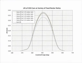
Transitioning back to the subject at hand – variations in cam lift curves introduced by applying fixed rocker ratio multipliers or dividers – and in spite of the possible pitfalls called out above, a fixed rocker ratio multiplier can provide a reliable data set for comparison with known cam data sets. For instance, consider the plot below. This is a plot of cam lift for a stock CDO cam (data courtesy of Comnoz) that has in turn been multiplied by a variety of fixed rocker ratios to illustrate where, and how much the valve lift curve might be distorted by such an undertaking. In general, at low lifts up to mid-lift the data is distorted minimally (minimally to me, hopelessly flawed to Snotzo) and lends itself well to comparison with other known valve lift curves. The distortion becomes greater as lift approaches the nose (but note that the 1.13 multiplier does in fact provide the factory quoted valve lift of 0.375”). In light of the foregoing, I believe the fixed multiplier approach provides a reasonable way for the less sophisticated practitioner (me) to compare unknown valve or cam lift curves to known curves for the purpose of identifying cam profiles.
 

Attachments

  • Early camshaft
    CDO cam - valve lift at various rocker ratios.webp
    61.4 KB · Views: 416
Reading through previous posts on this topic, I realise the general trend of posts have drifted away somewhat from the original subject, but if I may be allowed to continue on the present drift of this topic, I would like to expand somewhat on comments I have made earlier re measured data to 6 decimal places or better.

Pushrod valve train mechanisms are the most difficult to work with owing the the numerous areas where flexibility can occur, thus depriving the action at the valve from following precisely the dictates of the cam. To examine data to 4 places gives a basic indication for the lift curve, the first derivative will be reasonable for velocity, the second derivative is hard pressed to present acelleration in a truly meaningful manner, and the third derivative,jerk, is next to useless. And the problem with this is because jerk gives the best indication of the smoothness of the cam profile progression.

If I take data over consecutive degrees at 4 decimal places, by differentiation I arrive at figures for jerk, but in all probability the figures will all be identical. If the same basic data is now presented in it's original format of 6 decimal places, the differentiation will show meaningful figures for jerk, and the figures will in themselves give an indication of the smoothness of progression of the design. 8 places of decimals gets even better, and now it is possible to go to the 5th derivative, snap, and further examine the progression of the profile.

Examples, for 4 place data, two adjacent jerk figures would be something like -0.0002 and -0.0002
Same data but at 6 places, jerk would be something like -0.000017,-0.000015.
Same data but at 8 places, jerk would be something like -0.00001625, -0.00001536

This concentration on the 4th and 5th derivatives also needs some explanation. In a pushrod engine there is collected evidence to show that jerk can be a limiting factor for valve train control, and the figure generally used is 0.0009 mm/drg^3, or 0.00003543 in/deg^3. Furthermore, this criteria is applicable more to the valve closing side than it is to the opening.

There are Commando cams in circulation that are well within the above jerk reccomendation, but there are also some that aren't, and a notable cam in this latter respect is the PW3.

The fact that a cam is outside the recommended jerk range does not mean it will not be a good performer, in fact with the PW3 it is an excellent performer over a reasonable engine speed range, but if one tries pushing the engine speeds progressively up with the PW3 it will eventually become unstable, and will do so earlier than a cam that has a lower jerk rating. For the record, the PW3 I measured has positive jerk of 0.001268 mm/deg^3 and negative -0.001297 mm/deg^3. This latter negative figure is for that period when the valve has been accellerated to maximum, and is now slowing down as it continues on to peak lift, or on the closing side through the same period. By comparison, the Norris Magnum 70 has jerk values of 0.000572 mm/deg^3 and -0.000559 mm/deg^3, very easy on the valve train (if this is the only consideration - most probably it is not).

I hope this will explain why it is not possible to examine in any detail overlaid graphs of lift profiles, except for the most basic of reasons. To delve into actual designs, and gain some understanding of what lies behind the design as I hope to have adequately explained, is a whole lot more difficult.

To those who would like to learn more on the subject of cam design and manufacture, I can recommend Camshaft Reference Handbook by Don Hubbard, in all probability the best book yet on the subject, but a copy may be very difficult to obtain.
 
Status
Not open for further replies.
Back
Top