Preferred method for measuring valve spring pressure (2020)

Status
Not open for further replies.

acadian

VIP MEMBER
Joined
Mar 5, 2010
Messages
1,376
Country flag
I've previously set them up in the head using only the installed height figures, but I've got some beehive springs on the way, and I'll be using a press with a scale this time before installing them in the head, my plan is to try and achieve the poundage at specified height in the press using shims, but once installed in the head I can't think of a way to verify the setting. I've looked at some fancy in-head spring load gauges, but they're far too pricey and I doubt they'd even work on a brit cylinder head. Anyone have a tip they could share?
 
Call Don Morris, he did my heads for me and set my spring height. Same guy that dyno tunes Herb Becker's Norton Race bikes. Out of Mount Hope, Ontario. He mostly does Harley stuff now but he knows Norton's as well.
google " stay tuned systems inc."
 
A lot of race engine builders use the spring testing before installation process. Installed spring pressure measuring is good for a small block Chevy but you are right, very special tools needed for a Norton head to give any useful info!

I have spent time in Bruno Perlinski's workshop here in France with him demonstrating the process. He has made himself some better tools to measure installed height with the valve on the seat than I have. But he is shimming to measured figures on the seat with his preferred springs and preferred pressure. There is a long thread on here somewhere discussing valve spring pressures, but use what your supplier recommends

Essentially I am following the same process as Bruno, if without the confidence and finesse. It is consistent with the methods described by Jim Schmitt, and I am pretty sure Jim Comstock is doing much the same.

When you have the guage set up check pressure at intended installed height, but also do a check for pressure at full lift, which is best measured but can be calculated not forgetting the rocker ratio calculation.

Now you will know what happens as it goes over the nose.

When the head is fastened down check for coil bind.

If you are fitting these springs I guess you will also be planning to test valve to valve and valve to piston clearances.

Probably, you are going to 'build' the top half of the engine a few times before you are done!
 
That's helpful, thanks I had not considered the rocker ratio. My approach here is that the spring's rate is a constant variable, hence poundage at height is the same off or on the bike, the intervening variables will be rocker geometry and valve recession
 
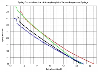
The image below should give you a feel for the general shape of force curves you are likely to see with progressive springs. Note that these are all heavier springs, so not to be confused with a Norton spring, but they still show the general characteristics of progressive springs. None of the curves are linear, as they all show varying degrees of curvature, but the amount of progression is relatively small until the spring is near solid.

If you generate a similar curve for your spring that’s really all you need to know about setting it up. Choose the seat force you desire, set-it up using a valve spring micrometer
in your head and then look at the plot you generated to see what open force will be at full valve lift.

Progressive Spring Characterization.jpg
 
Last edited:
The image below should give you a feel for the general shape of force curves you are likely to see with progressive springs. Note that these are all heavier springs, so not to be confused with a Norton spring, but they still show the general characteristics of progressive springs. None of the curves are linear, as they all show varying degrees of curvature, but the amount of progression is relatively small until the spring is near solid.

If you generate a similar curve for your spring that’s really all you need to know about setting it up. Choose the seat force you desire, set-it up using a valve spring micrometer
in your head and then look at the plot you generated to see what open force will be at full valve lift.

View attachment 17574

Helpful, thanks, and that tool looks nifty. The beehive's are from Kibblewhite, going in a hopped up Triumph 750, the install specs are fairly complete.

installed height: 1.370" - 1.380" @ 90lbs
189lbs @ .350 lift
220lbs @ .460 lift

Using that tool to get the baseline installed height I should be able to then verify the poundage on the press at the lift specs provided by Kibblewhite, triumph rocker ratio is apparently 1.125 : 1 so I think I'd be looking for:

189lbs @ .393
220lbs @ .517

Someone please correct me if I'm back-asswards here
 
Last edited:
From the Kibblewhite data you provided, the spring rate is ~ 282 lb/in. This rate is determined by examining the ratio of force to lift, i.e., the valve moved 0.350” and the force increased from 90 to 189 lb, or 99 lb increase in force. Thus the ratio of force to distance is 99 lb force/0.350 inch lift = 282 lb/in spring rate. With the spring rate known, you can add the seat pressure to any additional force that results from lifting the valve further to determine the force at any lift.

To provide an example, let’s assume you want to determine the total spring force at a valve lift of 0.393”. Let’s also assume you are starting with a seat force of 90 lb. Then if the valve is lifted an additional 0.393”, you multiply this lift by the spring rate and come up with an additional force of 0.393” x 282 lb/in spring rate = 111 lb force. This additional force is added to the seat force to obtain the total force at that lift, which is 90 + 111 = 201 lb force at a lift of 0.393”. The other lift point you provided, 0.517”, would have a total force of 90 lb + (0.517 x 282) = 236 lb force.

But…….. I’m quite certain that you will not be lifting your Triumph valve over 0.500”, so there is some confusion here as to what your valve lift will actually be for the cam you will be using. You needn’t be concerned with the rocker ratio for spring set-up. The only information you need to set-up the spring is valve motion, which is derived from the cam profile, lifter form and rocker ratio.
 
That's helpful, thanks I had not considered the rocker ratio. My approach here is that the spring's rate is a constant variable, hence poundage at height is the same off or on the bike, the intervening variables will be rocker geometry and valve recession

Valve recession and the specific valve variation from manufactring tolerances considering seating face and collet location, is taken into account by measuring the installed height when planning your shimming.

You shim to make the space you are putting the spring in the same dimension as the spring itself at the required seat pressure. That measurement will stay good for the life of the spring! Meaning when it changes significantly consider the spring to be at the end of it's life. (Though most likely if you took it out to check it, you were expecting to replace it anyway!)

I sent ages dealing with this one a while back concerned that my settings were part of component failure, so I know it is easy to overthink this one. Component compatibility in terms of springs validated appropriate for the job not an unknown supply, good quality valves, the correct followers for your cam of choice and a good oil should all be addressed.

Do the basics, check more than twice! And then go with it.
 
The image below should give you a feel for the general shape of force curves you are likely to see with progressive springs. Note that these are all heavier springs, so not to be confused with a Norton spring, but they still show the general characteristics of progressive springs. None of the curves are linear, as they all show varying degrees of curvature, but the amount of progression is relatively small until the spring is near solid.

If you generate a similar curve for your spring that’s really all you need to know about setting it up. Choose the seat force you desire, set-it up using a valve spring micrometer
in your head and then look at the plot you generated to see what open force will be at full valve lift.

View attachment 17574
Yep the tool is very nifty. It is basically what Bruno Perlinksi made for himself, from an old set of moped forks with a 1.0 metric pitch thread! but much prettier!

Being French, Bruno is metric!

But I think to use a tool like this in a Norton you would want one one sized around 1.2" to 1.6", you might have a little difficulty using a 1.4 to 1.8" Can anybody confirm having used one on a Norton head?

Might be better to get a 0.600". to 0.950" sized one and make a spacer of say 0.600" to use with it?
 
Last edited:
Yes, noticed the size range is not suitable, need 1.0-1.5 for brit bikes and that doesn't seem to be a thing. Also found some anecdotal evidence (youtube) claiming that these micrometers vary in their accuracy. I'll just measure installed height with an outside caliper and a small diameter spring to tension the valve and spring retainer in the seat.

I'll instead spend the money on a small spring pressure scale to use in a press.

I recently picked up a gently used Neway seat cutting set for $200, so I saved some scratch there
 
I think some folks here are overthinking. On this forum??? Never!

If you know what your installed height should be based on the spring mfgr's recommendation, put your valve in the head with a spring seat, a shortened Amal carb spring, collets and collar. Measure the height between the spring seat and the underside of the collar (i.e. the spring height only - not the collar or seat thickness). The Amal carb spring keeps tension on the retainer leaving lots of room to get in there and measure.
You can use a caliper, expanding bore gauge, ruler if you can get in there, or anything that can be accurately measured.

See a great example here: http://www.grumpysperformance.com/pic191.jpg

Let's say your spring height measures 1.380" and you want a 1.350" installed height- this means you need to shim .030" under the spring seat to get your desired installed height.

If you want to work from seat pressures, you can do it another way. Let's say you want 100# seat pressure. Using your spring pressure scale, press the spring to 100#, then measure the spring at this height. Ostensibly this would be your ideal installed height (assuming you wanted 100#). From there you can calculate the nose pressure by adding the cam lobe height and rocker ratio (1.13) and pressing your spring to this height, and measuring your poundage. Don't forget to leave and allowance for coil bind (usually at least .060 or more).

All fun stuff. Have a sharp pencil and paper handy, and take your time. Shims and phenolic heat spacers are very helpful here.
 
Y.......Also found some anecdotal evidence (youtube) claiming that these micrometers vary in their accuracy.....

The way to deal with that, assuming that following Kenny's comments you still want to own one :cool: ....

Use your spacer! Insert spacer then insert micrometer device and read off the numbers. Remove. Reset the numbers. Measure the total of the spacer and the micrometer device. A good vernier caliper will be accurate enough, because due to available shimming you are going to compromise a little anyway!

Jim Schmitt starts with a 1.0" spacer and only measures the fraction (say 0.350") in any case!
 
Great advice, thanks Kenny and Steve, probably best for me to record the cam lift before stripping the head off the bike.
 
I just use a set distance piece and add what the dial gauge says for measuring.
Accurate enough unless you are aiming for the moon and prepared to recheck the assembled height pressure again in X amount of running time.

Preferred method for measuring valve spring pressure (2020)
 
Status
Not open for further replies.
Back
Top