How does a Compression "Leak Down" tester work?

Status
Not open for further replies.
Aircraft engines are larger of course so I ordered my leak down tester with the optional smaller orifice.
 
So if a person bought a test rig without knowing the correct orifice needed for the size bore and engine tested the test could be skewed? Also how can a person read a 100psi gauge down to 1 psi and the gauge is only rated at +/- 2% accuracy ?


How does a Compression "Leak Down" tester work?
 
In the case of the ad in post #23, above, wouldn't you just go by the spec on the chart - based on bore size?

TBH, although we used Snap On leak testers extensively, I don't recall there ever being a "choice" of orfice size. Maybe there was no choice or the tech guy who bought the tools knew it and selected the correct version for what we did.

As far as reading the gauge, you are correct, of course. Just like a torque wrench, the readings are only as accurate as the tolerance of the tool itself. So comparing leak-down readings on different tools could produce a different reading.

I recently saw a digital leak down tester at a shop that shows a precise reading but I don't know if the tester itself is any more or less accurate than an analog version or if it just appears that way because it shows a specific number. A digital pressure gauge is just an analog device with a digital converter/gauge attached. Certainly easier to read but about 5-6x the cost of the analog gauges in the post #23 ad and about 2x the price of a Snap-On analog.
 
How does a Compression "Leak Down" tester work?
 
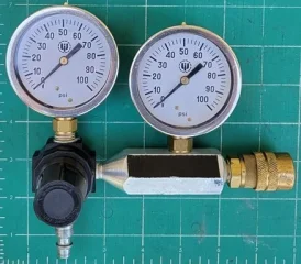
This thread has provided an interesting discussion on leak-down testing. I hope to add to our understanding of such measurements by providing recent results of leak down tests performed on an engine I’ve been working on. The marque is irrelevant aside from the fact that it has 2 cylinders, a 2.75” bore, and rings with excessive end-gap. The particular leak-down tester employed in this undertaking was made by a friend and has a provision to alter the size of the “bleed orifice” between the 2 gauges in a systematic way. More specifically, a Mikuni air correction jet is employed to vary the orifice size, thus there is a full range of appropriate size orifices available. The specific air correction jets employed in this experiment were a 0.5 (0.5 mm orifice, ~ 0.0197” dia) and a 1.0 (1.0 mm orifice, ~0.0394” dia). The 1.0 mm jet was chosen because it would be within 0.0006” dia of the standard 0.040” bleed orifice used for an engine of this size in the FAA test protocol, and referenced earlier in this thread. An image of the tester is shown below, where the air jet is installed in the necked down section of the body where it threads into the regulator.

compression leak down tester.jpg

Because the discussion in this thread has covered both high- and low-pressure testers, and discussion/debate has ensued on the merits thereof, I decided to perform the leak-down test at several different pressures, specifically 100, 50 and 25 psi with each of the 2 orifice sizes recited above on both cylinders.

Before discussing the test results I’d like to make a few points regarding the leak-down test, especially in light of the 2 orifice sizes employed here. If the tester is fit with a 0.5 mm bleed orifice (between 1st and 2nd gauge) this is the leak rate that cylinder leakage is compared to. Let’s now consider what happens when the bleed orifice is increased in size, e.g., changing it from a 0.5 mm orifice to the 1.0 mm orifice. Although the orifice diameter has only doubled in size, the orifice area increases by 4X, thus, in use we are now comparing engine leakage to a reference leak 4X larger than when the small orifice was employed, and in so doing have significantly decreased the sensitivity of the leak-down test. Earlier in this thread reference was made to the 0.040” orifice being suitable for engines with less than 5” bore, whereas a 0.060” orifice was required for engines of greater than 5” bore. Here again, going from a 0.040" orifice to a 0.060" orifice the dia only increases by 50%, but the orifice area increases by 2.25X, so again large step down in leakage sensitivity, which is consistent with use on a larger cylinder with larger ring gaps, more surface area, and hence, more leakage .

Hopefully the foregoing discussion reinforces that the smaller the bleed orifice in the tester the more discriminating the leak-down test becomes. And to the contrary, the larger the bleed orifice, the less sensitive the leak-down test becomes.

The person that built the subject leak-down tester employed here was working on 600 cc crotch rocket race engines at the time (small engines/small bores) and was unhappy with the results he was getting from his Snap-On leak-down tester, as the results were not as discriminating as he desired (everything looked too good). Thus, he fit the gauge with the 0.5 mm orifice to be more discriminating. As I started performing a standard 100 psi leak down test on my project I was initially horrified by the amount of leakage observed - in the range of 20-50% - and truly concerned about the soundness of the engine! Shortly thereafter I recalled that this tester was fit with the small bleed orifice, thus was highly discriminating, and in turn likely responsible for the high leakage observed. It was at this moment that I decided to perform some systematic screening tests at the pressures recited above with both orifices. These tests were conducted on a cold engine and since I was seeking differences in readings rather than absolute values, I reasoned that I needn’t slave over a hot engine to generate useful data.

Before performing leak-down tests on the engine I wanted to see how the gauge alone responded when pressurized with no outlet. This would point out any disparities in readings from gauge to gauge as well as possibly identifying any leaks in the system. At test pressures of 100, 50, and 25 psi, and with both the large and small orifice, the 2nd gauge gave readings of 98, 49.5 and 25 psi respectively. Thus, a small correction was required at the 2 higher test pressures and was made on the tabulated results.

With one cylinder set at TDC, the test was 1st conducted with the 0.5 mm orifice and immediately thereafter the orifice was changed to 1.0 mm and the test repeated. The results of these tests are presented graphically below.

Plot of leak-down results.jpg


The results in the graph show that with the standard large 1 mm orifice (red data) leakage values for both cylinders are excellent and average in the range of 2-3%, and that cylinder 2 is slightly tighter across the board than cylinder 1. The results also show that with the large bleed orifice the test is relatively insensitive to test pressure as the results are nearly identical at all test pressures. I breathed a sigh of relief after seeing these results and realizing that the test engine was in fact nice and tight with very low leakage, vs the initial observations with the small orifice that showed large leakage rates.

When the orifice was changed to the smaller (0.5 mm) more discriminating orifice the results were dramatically different exhibiting significant leakage values and very clearly showing the superiority of cylinder 2 to cylinder 1. With the smaller orifice the test also exhibited a significant dependence on test pressure, i.e., leakage increased with decreasing test pressure.

All of the above results were repeated several times and the same values were recorded each time the test was performed. Hopefully the above discussion clarifies how some of the testing parameters employed in leak-down testing impact the results. Furthermore, the results might guide someone wanting to conduct a slightly more discriminating leak down test if the need arose.

As always, comments, questions, corrections, etc welcomed.

Edit - Removed the word accurate in the above text
 
Last edited:
Since this was a real test on a real engine, were you able to identify where the leak was? Besides having a quantifiable number, the beauty of a leak test is hearing that hissing sound from the intake, exhaust, or crankcase breather.
 
This thread has provided an interesting discussion on leak-down testing. I hope to add to our understanding of such measurements by providing recent results of leak down tests performed on an engine I’ve been working on. The marque is irrelevant aside from the fact that it has 2 cylinders, a 2.75” bore, and rings with excessive end-gap. The particular leak-down tester employed in this undertaking was made by a friend and has a provision to alter the size of the “bleed orifice” between the 2 gauges in a systematic and accurate way. More specifically, a Mikuni air correction jet is employed to vary the orifice size, thus there is a full range of appropriate size orifices available. The specific air correction jets employed in this experiment were a 0.5 (0.5 mm orifice, ~ 0.0197” dia) and a 1.0 (1.0 mm orifice, ~0.0394” dia). The 1.0 mm jet was chosen because it would be within 0.0006” dia of the standard 0.040” bleed orifice used for an engine of this size in the FAA test protocol, and referenced earlier in this thread. An image of the tester is shown below, where the air jet is installed in the necked down section of the body where it threads into the regulator.

View attachment 81411

Because the discussion in this thread has covered both high- and low-pressure testers, and discussion/debate has ensued on the merits thereof, I decided to perform the leak-down test at several different pressures, specifically 100, 50 and 25 psi with each of the 2 orifice sizes recited above on both cylinders.

Before discussing the test results I’d like to make a few points regarding the leak-down test, especially in light of the 2 orifice sizes employed here. If the tester is fit with a 0.5 mm bleed orifice (between 1st and 2nd gauge) this is the leak rate that cylinder leakage is compared to. Let’s now consider what happens when the bleed orifice is increased in size, e.g., changing it from a 0.5 mm orifice to the 1.0 mm orifice. Although the orifice diameter has only doubled in size, the orifice area increases by 4X, thus, in use we are now comparing engine leakage to a reference leak 4X larger than when the small orifice was employed, and in so doing have significantly decreased the sensitivity of the leak-down test. Earlier in this thread reference was made to the 0.040” orifice being suitable for engines with less than 5” bore, whereas a 0.060” orifice was required for engines of greater than 5” bore. Here again, going from a 0.040" orifice to a 0.060" orifice the dia only increases by 50%, but the orifice area increases by 2.25X, so again large step down in leakage sensitivity, which is consistent with use on a larger cylinder with larger ring gaps, more surface area, and hence, more leakage .

Hopefully the foregoing discussion reinforces that the smaller the bleed orifice in the tester the more discriminating the leak-down test becomes. And to the contrary, the larger the bleed orifice, the less sensitive the leak-down test becomes.

The person that built the subject leak-down tester employed here was working on 600 cc crotch rocket race engines at the time (small engines/small bores) and was unhappy with the results he was getting from his Snap-On leak-down tester, as the results were not as discriminating as he desired (everything looked too good). Thus, he fit the gauge with the 0.5 mm orifice to be more discriminating. As I started performing a standard 100 psi leak down test on my project I was initially horrified by the amount of leakage observed - in the range of 20-50% - and truly concerned about the soundness of the engine! Shortly thereafter I recalled that this tester was fit with the small bleed orifice, thus was highly discriminating, and in turn likely responsible for the high leakage observed. It was at this moment that I decided to perform some systematic screening tests at the pressures recited above with both orifices. These tests were conducted on a cold engine and since I was seeking differences in readings rather than absolute values, I reasoned that I needn’t slave over a hot engine to generate useful data.

Before performing leak-down tests on the engine I wanted to see how the gauge alone responded when pressurized with no outlet. This would point out any disparities in readings from gauge to gauge as well as possibly identifying any leaks in the system. At test pressures of 100, 50, and 25 psi, and with both the large and small orifice, the 2nd gauge gave readings of 98, 49.5 and 25 psi respectively. Thus, a small correction was required at the 2 higher test pressures and was made on the tabulated results.

With one cylinder set at TDC, the test was 1st conducted with the 0.5 mm orifice and immediately thereafter the orifice was changed to 1.0 mm and the test repeated. The results of these tests are presented graphically below.

View attachment 81412

The results in the graph show that with the standard large 1 mm orifice (red data) leakage values for both cylinders are excellent and average in the range of 2-3%, and that cylinder 2 is slightly tighter across the board than cylinder 1. The results also show that with the large bleed orifice the test is relatively insensitive to test pressure as the results are nearly identical at all test pressures. I breathed a sigh of relief after seeing these results and realizing that the test engine was in fact nice and tight with very low leakage, vs the initial observations with the small orifice that showed large leakage rates.

When the orifice was changed to the smaller (0.5 mm) more discriminating orifice the results were dramatically different exhibiting significant leakage values and very clearly showing the superiority of cylinder 2 to cylinder 1. With the smaller orifice the test also exhibited a significant dependence on test pressure, i.e., leakage increased with decreasing test pressure.

All of the above results were repeated several times and the same values were recorded each time the test was performed. Hopefully the above discussion clarifies how some of the testing parameters employed in leak-down testing impact the results. Furthermore, the results might guide someone wanting to conduct a slightly more discriminating leak down test if the need arose.

As always, comments, questions, corrections, etc welcomed.
wonderful insight, however I still have a problem with reading a 100psi gauge with 2 psi graduations down to 2 psi.
 
Hopefully the foregoing discussion reinforces that the smaller the bleed orifice in the tester the more discriminating the leak-down test becomes. And to the contrary, the larger the bleed orifice, the less sensitive the leak-down test becomes.

so this boils down to, like dyno testing there can be no real numbers comparisons between different technicians and test equipment
 
Since this was a real test on a real engine, were you able to identify where the leak was? Besides having a quantifiable number, the beauty of a leak test is hearing that hissing sound from the intake, exhaust, or crankcase breather.
Yes, the leakage was very clearly occurring only at the rings as evidenced by slight airflow at the timing plug hole with the carb and exhaust system being totally silent.
 
Hopefully the foregoing discussion reinforces that the smaller the bleed orifice in the tester the more discriminating the leak-down test becomes. And to the contrary, the larger the bleed orifice, the less sensitive the leak-down test becomes.

so this boils down to, like dyno testing there can be no real numbers comparisons between different technicians and test equipment
The standard FAA orifice would be 0.040" for less than 5" bore, so I suspect the majority of testers made over the years for automotive and motorcycle applications would have this orifice in them. None would have a 0.020" orifice since that would always provide dramatically higher leakage, i.e., way out of the norm, and none would have the 0.060" orifice since that would likely show zero leakage unless an engine was absolute junk. That said there should be reasonable agreement between leak-down testers having the same orifice size. IMHO the FAA leak down test is a rather coarse tool, yet tells exactly what a mechanic wants/needs to know about cylinder sealing and the need for attention.

However, there are myraid other factors to consider in leak-down testing that can convolute results, such as....

Is the engine a fresh unrun build or used?
When testing on a new engine, were the valves lapped, were the rings soaked with engine oil, or were the "bores only" wiped with a very thin layer of oil when assembled?
How long was the test run? 5 sec? 5 minutes? 1/2 hr?
Did the test run long enough to force oil off the rings and did leakage increase thereafter?
Was the engine hot, lukewarm or cold when the test was performed, and how badly does the bore distort at any of these temperatures?
Is leakage higher when the engine is hot or cold?
And on and on and on.....

So yes, there are likely reproducibility issues with the test, yet it has been used successfully for many decades, and the test yields plenty of useful information even if you can't achieve an exacting round robin type results comparison.

My $0.02
 
However, there are myraid other factors to consider in leak-down testing that can convolute results

I like the methodology you employed and the way you presented the results, well done!

I have a Matco tester and will be looking to see if it has an interchangeable discharge orifice, however, my tests are run on a fresh engine that has at least 500 miles on it when it is warm to hot. I work up to 80 psi and have been rewarded with leak down rates under 10% with a high degree of equality on both sides; this tightens up a bit after 1000 miles.

Best.
 
I'm not sure why a smaller orfice would be considered "more accurate." If you change the sizes of the orfice (or pressure), you are changing the parameters of the instrument to something OTHER than "standard." IOW, claiming a different orfice/different pressure is more "accurate" because it shows more leakage doesn't make it "accurate" unless you define the standard for that orfice/pressure. At some low enough pressure level, there would naturally be almost 100% leakage!

As far as finding the leak(s) itself - you don't need a gauge set, just compressed air. The gauge set simply allows a "measurement" to be applied. If different instruments with different orfices/pressures are used, the measurement is different. The advantage of higher pressure is that it is much easier to detect the where the leakage is coming from. But from a measurement point of view, it makes no difference what sort of instrument you use AS LONG as it has some standard reference. If a 100PSI/larger orfice tester shows 10% leakage and a 20PSI, small orfice tester shows 30% leakage, which one is "correct?" There would have to be a correlation chart or whatever to be able to compare results.

Otherwise as noted earlier, there would be absolutely no use in measuring leak down because the results are meaningless without a standard by which to compare them.
 
Last edited:
Actual aircraft mechanic here so here's what we do:

Using 80 PSI input through the orifice others have discussed and with the piston at TDC we look for what the second gauge reads. Having the advantage of the leverage of the propeller we rock the piston to get all of the rings to seat. Often what seems to be bad ring leakage will turn out be very little leakage at all with a few tugs either way on the prop. Generally what was considered acceptable for years was 80/60 with no leakage past valves. An engine that came up low often would come up good after a brief run or flight as long as there was no valve leakage.

Large bore Continental engines often flunked even though they seemed to be running well and producing good power. The manufacturer did some testing and found that the test we were using was condemning actual good cylinders. They came up with a master orifice that one attaches to the output side that dictates the acceptable low of the day - atmospheric pressure changes dictate the difference. When used on my calibrated tester the low of the day is generally in the low 40s PSI range, which means that years ago I, and every other mechanic, changed a lot of good cylinders. Continental's Service Bulletin specifies NO valve leakage AND a borescope is required at every inspection.

My take on this for a bike: Don't get too carried away with readings. Use it to see if the valves are sealing and that there's not a whole lot of leakage past the rings. If the rings seem to be leaking but the bike doesn't blow blue smoke take it for a ride and try it again. Someone mentioned above that just using regulated air pressure will tell you much of the same, which brings up a funny memory:

I was working a a shop that worked on whatever rolled up to the door. One of the other guys was working on a T28D, a '50s Navy trainer, carrier version, short prop, tail hook. Anyway, he had a dead cylinder and could hear it whistling past a valve so was going to "stake" it with full shop air in the cylinder suspecting it was a chunk of lead. Aircraft gas is so full of lead, especially before 100LL, that there often would be chunks of lead breaking off the chamber and holding valves open. They would blow out naturally when running.

Anyway, the T28 had an R1820 Wright, 1820 ci on 9 cylinders so they're trash can sized. The other guy asked me to hold the prop saying "don't worry, it's right at TDC" Yeah, no. It wasn't and as soon as he lined up his soft hammer on the exhaust valve it sealed and the engine being geared with a trash can cylinder and short prop picked me right off the floor. Everyone was amused.
 
First time I ever did a leak down - I was 15 or thereabouts at the time - the mechs did a typical "Screw with the kid" thing. Told me how to set up for a leak down - TDC, etc. When I opened the air valve, the ratchet/socket I had used to put the engine at TDC (and left on the crank bolt) went flying sideways and scared the heck out of me. This was, of course accompanied by much laughter. But I learned a good lesson about TDC and the fact that the crank being precisely at the TDC mark DOES NOT mean the piston is precisely at TDC! ;)
 
  • Like
Reactions: baz
While looking for something unrelated I just stumbled upon this, which seems to validate my above post:
 
Status
Not open for further replies.
Back
Top