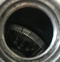
I did a post called "Linear Piston Travel and Advance Degrees." Below is the chart. It is compensated for the spark plug hole angle. I have a dial indicator that screws into the spark plug hole. The tip is ground into a rounded ball which slides across the piston easily. I find TDC by turning the rear wheel in high gear until the dial indicator is at it's peak. This method allows you to find thirty one degrees or twenty and any in between without taking off the rotor or the primary cover. Just set the piston .362 inches (9.205mm) before top dead center and run around the other side to see if your mark is correct on the primary cover degree markings. What to do it is is off is another story and I would try it several times to make sure the dial indicator is repeating accurately.
31°= .320" (8.127mm) BTDC (Before Top Dead Center), 0.362” (9.205mm) (compensated for the 62° spark plug hole angle.)
30°= .300" (7.630mm) BTDC, .340” (8.642mm)
29°= .281" (7.147mm) BTDC, .319” (8.095mm)
28°= .263" (6.678mm) BTDC, .298” (7.564mm)
27°= .245" (6.224mm) BTDC, .278” (7.049mm)
26°= .228" (5.784mm) BTDC, .258” (6.551mm)
25°= .211" (5.359mm) BTDC, .239” (6.070mm)
24°= .195" (4.949mm) BTDC, .221” (5.605mm)
23°= .179" (4.554mm) BTDC, .203” (5.158mm)
22°= .164" (4.174mm) BTDC, .186” (4.728mm)
21°= .150" (3.810mm) BTDC, .170” (4.315mm)
20°= .136" (3.462mm) BTDC, .154” (3.921mm)
The figures in GREEN are corrected for the 62° angle of the spark plug hole. When the gauge measures 1 inch of travel the piston will have moved .8829" down so the gauge needs to read more than the actual piston travel to give you the actual piston travel. According to Jim Comstock the crank offset he has measured was only .5 to 1.0mm on 750 and 850 Commando engines which is not much. And, of course, if the piston is domed or dished the dial indicator will be hitting a different part of that dome or dish at the different distances from TDC as it moves across the piston because of the 62° angled spark plug hole.
(One small disclaimer: If you are running rods of any length other than stock then these numbers will not work for your engine. )

")