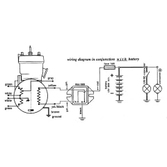
Ammeter Wiring and Typmanium voltage regulator

Status
Not open for further replies.

jms

VIP MEMBER
Joined
Jul 26, 2005
Messages
265
Country flag
I've got a very early 1968 " Widow Maker" Commando that I picked up 18 years ago. At the time it was a work in progress and had been converted to a sort of Production Racer Replica. The wiring on the bike had been converted to negative ground and the charging system appears to be a two wire alternator combined with a Tympaniun voltage regulator and capacitor. All of the wiring has been beautifully done. I recently added the Production Racer bracket that is held in place by the obsolete upper triple tree handlebar brackets, which know incorporates the Wipac Tricon switch, Ammeter, and air lever. I've wired the Tricon and all lights and horns work. One odd thing that I did run across is that the Tympanium unit only has 3 wires. Two yellow, each going to the Alternator wires, and 1 black that goes to the capacitor. In all of my searches, I have yet to find a three wire Tympanium unit, so I'm not quite sure how this is working. That said I am having trouble wiring the ammeter in such a way that it will work. The original wiring diagram for this bike appears to show positive ground with the negative lead from the battery going to the plus side of the ammeter and the negative side of the ammeter going to the ignition switch and then the rectifier. Given the bike has been switched to negative ground I am assuming that the positive lead from the battery now goes to plus side of the ammeter but am unsure where the negative side of the ammeter should go as the rectifier has obviously been removed. Any ideas? Thanks in advance.
 
The Tympanium must be earthing itself through the body/mounting bolt, Briggs and Stratton use Tmpaniums and could be one of theirs and some do earth using the body/bolt. If it is then connect the other side of the ammeter to the mounting bolt.
 
+1 with @kommando

Also, Rotax use Tympaniums and ground out to negative through the heatsink

Ammeter Wiring and Typmanium voltage regulator
 
With negative earth you'll want the regulator and load (ignition switch) on the plus terminal of the ammeter and the minus terminal to the battery positive. This way it will read plus when charging.
 
Maylar... thanks for the clarification. Just to be clear can you confirm that the following is correct?
1. One wire from the + side of the battery to the ignition switch
2. A jumper wire from the ignition switch to the + side of the ammeter.
3. A wire from the regulator to the + side of the ammeter. In my case because my Tympanium only has three wires, the only regulator wire available to hook to the ammeter is the one that connects to the Capacitor. The other two wire to the alternator. Presumably the grounding of the Tympanium unit is through the mounting hardware as Kommando suggests.
4. One wire from the + side of the battery to the - side of the ammeter.

Thanks again everyone for the help!
 
Personally, I really don’t like Ammeters - they can be a very temperamental weak link, that really doesn’t tell you anything too useful.

Unless you use a shunt, everything electrical goes through the ammeter, so if it fails, so does your bike.

Maybe consider running a Voltmeter instead - it goes across + and - instead of inline, and in my opinion gives you more useful info without the risk!
 
Gtiller That's a thought! Do you know of anyone that sells a nice looking quality 1-3/4" voltmeter
 
"Do you know of anyone that sells a nice looking quality 1-3/4" voltmeter?"

An often-asked question...
 
Personally, I really don’t like Ammeters - they can be a very temperamental weak link, that really doesn’t tell you anything too useful.

I disagree. An ammeter shows the direction of current flow through the system, so it shows your bike's rotor/stator is working, it shows your rectifier is working and it shows your zener diode is working too. The needle will also pulse if you leave your blinker on and don't notice the bulb flashing in daylight.

Unless you use a shunt, everything electrical goes through the ammeter, so if it fails, so does your bike.

Maybe consider running a Voltmeter instead - it goes across + and - instead of inline, and in my opinion gives you more useful info without the risk!

All the rest of what Gtiller said above is true. A voltmeter pretty much tells you all the same things an ammeter tells you (if you know how to interpert it) with much less risk to your system, and the voltmeter can be wired parallel where as the ammeter is wired in series so when it dies, you're dead in the water.

*I've run an ammeter for 30 years with no problems, so I am probably bias towards them.
 
Maylar... thanks for the clarification. Just to be clear can you confirm that the following is correct?
1. One wire from the + side of the battery to the ignition switch
2. A jumper wire from the ignition switch to the + side of the ammeter.
3. A wire from the regulator to the + side of the ammeter. In my case because my Tympanium only has three wires, the only regulator wire available to hook to the ammeter is the one that connects to the Capacitor. The other two wire to the alternator. Presumably the grounding of the Tympanium unit is through the mounting hardware as Kommando suggests.
4. One wire from the + side of the battery to the - side of the ammeter.

Thanks again everyone for the help!


No.

Positive battery terminal to inline fuse. Other end of the fuse goes to the ammeter negative (and also to the horn, pre-71). Positive ammeter terminal goes to ignition switch and also the charging system and regulator. The schematics are in the Commando Workshop Manual, available online.
 
Personally, I really don’t like Ammeters - they can be a very temperamental weak link, that really doesn’t tell you anything too useful.

Unless you use a shunt, everything electrical goes through the ammeter, so if it fails, so does your bike.

Maybe consider running a Voltmeter instead - it goes across + and - instead of inline, and in my opinion gives you more useful info without the risk!

The wiring complexity is certainly a valid argument against ammeters. Heavy guage wire to the headlight shell and back. But as for usefulness, there's a reason why ammeters were used by the factory. The most failure prone part of an electrical system is the battery, and an ammeter gives the best indication of whether it's being charged or not.

This, however, must be balanced against a design where the charging system is unable to keep up with demand at low engine RPM. Unlike a "real" charging system where you get 14 volts even at idle regardless of battery condition, our Nortons' battery has to take over - and in that case, a voltmeter is just as useful and much simpler to use.

I know I've seen voltmeters that fit into the same hole -
 
What gauge wire should you use while wiring up an Ammeter?
 
"Do you know of anyone that sells a nice looking quality 1-3/4" voltmeter?"

An often-asked question...

yes, it is. I asked once, the responses lead me to a solution I could live (well) with.

I spent a few hours web crawling and on the phone looking for a 1 5/8" voltmeter and finally gave up. Advanced Auto Parts had one that was 1 1/2" but had the initial quality (to use a J.D. Powers term) of dog shit and looked like it would shake to pieces before you got down the road a mile.

One of the members turned me on to an English vendor that offers a very cool LED unit that fits into a warning light bezel and has signal modes that indicate system voltage.

16 gauge wires are what the Norton was born with. The exception is the MK3 starter circuit high current wires ( I could be wrong, but it's comforting to know that if I am some one will jump me). I sell 120, 180 and 200 watt reg/rec units that all have 16 gauge inputs and outputs. When I wire a bike from scratch I like to run a 14 gauge power wire to the head light shell and use a relay for the horn. I also use the Centech AP-1 5 gang fuse block which gets main power from a 12 gauge wire from the battery; probably overkill, but give me extra bandwidth to worry about something else...
 
Ammeter is a good instrument if you understand it. But it takes a bit of technical knowledge to know what it's telling you. Kind of the same with a voltmeter, but the VM is less technical. Neither will tell you something if you are expecting something different than what you think you may know.
 
Status
Not open for further replies.
Back
Top